
Nissan Armada 2025-2026 Service and Repair Manual: Removal and Installation
REMOVAL
WARNING:
CAUTION:
Never grab and deform the boots
 of the air spring when remove and installing. If deformed, return it without stretching.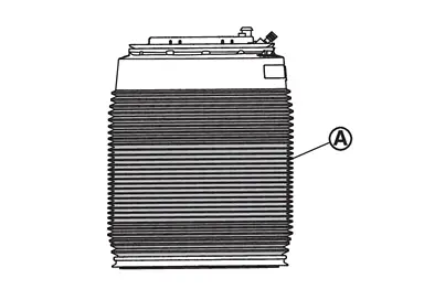
Start engine.
Turn OFF the electronic air suspension function. Refer to Operation.
Stop engine.
Lift up the vehicle.
Remove rear tire. Refer to ROAD WHEEL TIRE : Removal & Installation.
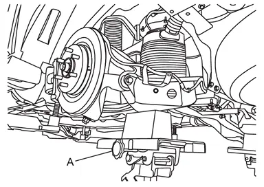
CAUTION:
Never damage rear lower link.
Check the stable condition when using a suitable jack.
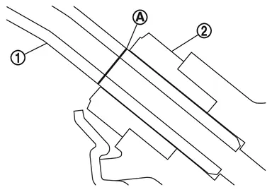
Apply the matching marks to the air tube  when replacing air connector
  .
.
Loosen the air connector and perform air bleeding.
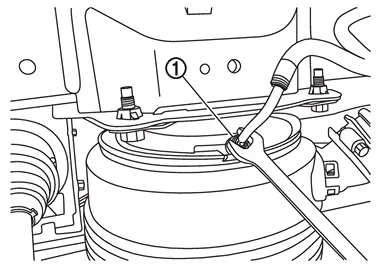
CAUTION:
Be careful since air flows swiftly from air tube.
Loosen the air connector slowly.
Never disconnect the air connector until the air completely bleeds.
When reusing the air connector , remove air tube and air connector together to air spring  .
.
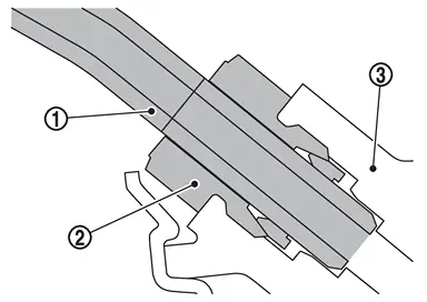
CAUTION:
Never damage air connector, air adapter, and air tube.
When reusing air connector, never remove air tube from air connector.
 NOTE:
NOTE:
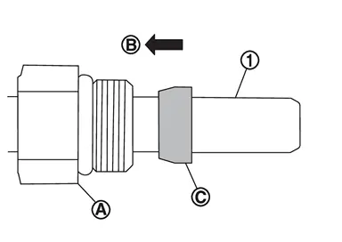
CAUTION:
Never damage air tube.
Remove the air connector part from the air tube .
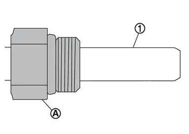
CAUTION:
Never damage air tube.
Loosen clamp , and separat air suspension duct assembly from duct part  of air spring .
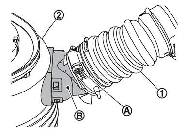
CAUTION:
Be careful not the duct parts come off from the air spring when working.
Put matching marks
on the air spring and the air suspension duct assembly before rsepareting the air suspension duct assembly.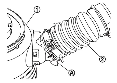
Remove rear height sensor. Refer to Removal and Installation.
Loosen rear lower link mounting nuts (frame side).
Separate rear lower link from axle housing.
Remove air spring from upper spring seat, follow the procedure below.Turn the air spring in the direction of the arrow ( ) so that the notch of the upper spring seat and the air connector hole are in the same direction.
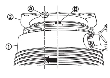
from the upper spring seat in direction .
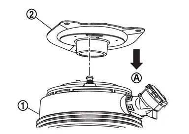
CAUTION:
Completely remove the butyl adhere on the air spring when reusing the air spring.
Lower suitable jack, and remove air spring from rear lower link.
CAUTION:
Check the stable condition when using a suitable jack.
Never damage rear lower link.
Remove lower spring seat from air spring.
CAUTION:
Remove upper spring seat mounting bolts, and remove upper spring seat.
Remove rear lower link mounting nut, eccentric disc, and adjusting bolt from frame, and remove rear lower link.
Remove air suspension LH/RH duct assembly, air suspension duct assembly, and brckets if necessary.
Perform inspection after removal. Refer to Inspection.
INSTALLATION
Install air suspension LH/RH duct assembly, air suspension duct assembly, and brckets if necessary.
Install rear lower link, rear lower link mounting nut, eccentric disc, and adjusting bolt to frame.
Install upper spring seat.
CAUTION:
Never reuse upper spring seat.
Install lower spring seat to air spring , align the angles of the elongated hole of the lower spring seat and the elongated hole of the air spring.
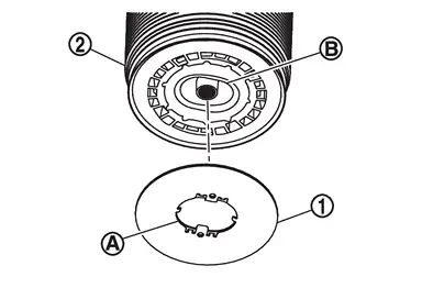
CAUTION:
Never reuse lower spring seat.
The center line
of the lower spring seat and the center line of the air spring should vary within ±3.5 degrees. 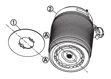
Install the claw part
of lower spring seat so that it does not interfere with the air spring.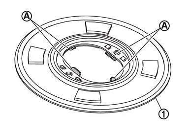
Install air spring to upper spring seat, follow the procedure below.Using the notch of the upper spring seat as a guide, insert the pin part of the air spring into the hole  of the upper spring seat.
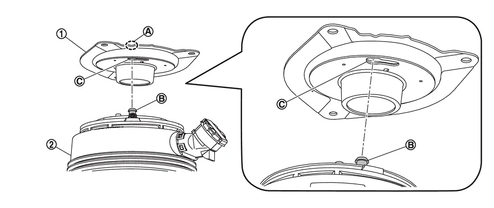
CAUTION:
Never let foreign materials entered into parts.
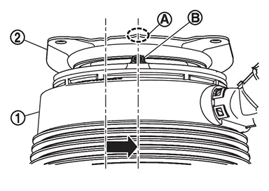
in the direction of the arrow ( ), and install it so that the protrusion on the upper spring seat and the air connector hole are in the same direction.
Set suitable jack under rear lower link, and jack up until air spring seats to the lower link without damaging the air spring.
CAUTION:
Check the stable condition when using a suitable jack.
Never damage rear lower link.
Never damage air spring.
Install rear lower link to axle housing.
CAUTION:
Never reuse mounting nut.
Tighten rear lower link mounting nuts (frame side).
CAUTION:
Never reuse mounting nut.
Install rear height sensor. Refer to Removal and Installation.
Apply soapy water to the duct part of air spring.
Install air suspension duct assembly to duct part of air spring , and tighten clamp .
CAUTION:
Align matching marks
on the air spring and the air suspension duct assembly before installing the air suspension duct assembly.
When reusing the air connector, install air tube and air connector together to air spring .
CAUTION:
Never damage air connector and air tube.
Never remove the vinyl tape until installing the air tube and air connector.
Never let foreign materials entered into parts.
When replaced the air connector, follow the procedure below.Install air connector to air spring Insert the air tube straight into the air connector to the marked point which is applied when removing.
CAUTION:
Securely insert the air tube with no damage and twist.
Never remove the air connector cover until air tube is installed.
Never let foreign materials entered into parts.
Start engine.
Use CONSULT and fill the inner pressure of air spring to 3.3 bar. Refer Work Support.
Remove suitable jack from rear lower link.
Stop engine.
Install rear tire. Refer to ROAD WHEEL TIRE : Removal & Installation.
Lift down the vehicle.
Start engine.
Perform pressure measurements using CONSULT. Refer to Work Support.
NOTE:
Confirm that "Air suspension internal pressure judgement" is OK.
Perform the height sensor calibration using CONSULT. Refer to Work Support.
Use CONSULT and vehicle to the normal height. Refer to Work Support.
Turn ON the electronic air suspension function. Refer to Operation.
stop engine.
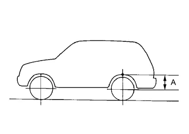
Perform final tighting of rear lower link by the following procedures.Measure between wheel center and fender arch (A).
NOTE:
Note the measurements.
. (axle housing ball joint fastening part).
CAUTION:
Never damage threaded part of ball joint.
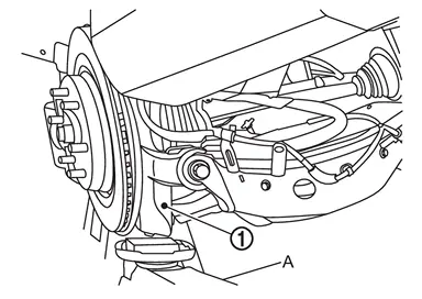
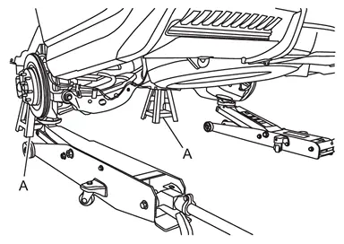
CAUTION:
Never damage axle housings.
Check the stable condition when using a suitable jack.
Never float the vehicle.
NOTE:
Jack up left and right at the same time.
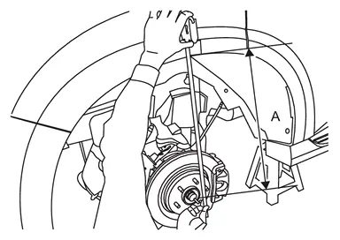
CAUTION:
Check the measurements are within +20 mm (0.79 in) from step a.
If the measurements are +20 mm (0.79 in) or more, perform step f again.
Perform inspection after installation. Refer to Inspection.
 Exploded View
Frame Upper spring seat Air spring Adjusting bolt Eccentric disc Rear lower link Axle housing Lower spring seat Air suspension duct assembly Air suspension LH duct assembly Air suspension RH d ...
 Inspection
INSPECTION AFTER REMOVAL
Check rear lower link, bushing and air spring for deformation, crack, and damage. Replace it if necessary.
INSPECTION AFTER INSTALLATION
Confirm to close the hood.
Always chec ...
Other materials:
Removal and Installation
REMOVAL
Remove back door trim. Refer to Removal and Installation.
Remove mounting nuts .
Remove mounting bolts .
Disconnect rear washer tube C .
CAUTION:
When washer tube is disconnected, washer fluid may come out so prepare a container to receive washer fluid and never allow washer fluid to b ...
Refilling
WARNING:
The ignition switch OFF.
Recommended fluid and capacity: Refer to Fluids and Lubricants.
CAUTION:
Carefully fill the fluid. (Fill up for approximately 3 minutes.)
Leave the vehicle for 3 minutes, and check the fluid level again.
Install filler plug on transfer and tighten to the specif ...
FUEL LEVEL SENSOR UNIT, FUEL FILTER AND FUEL PUMP ASSEMBLY : Removal & Installation
WARNING:
WARNING:
Be sure to read “General Precautions� when working on the fuel system. Refer to GENERAL PRECAUTION : Precautions.
REMOVAL
Check fuel level on a level ground. If the fuel level is 7/8 of the fuel tank (full or nearly full), draw appropriate amount of fuel from the fuel tank.
...

0.0053