
Nissan Armada 2025-2026 Service and Repair Manual: ROAD WHEEL TIRE : Adjustment
WARNING:
BALANCING WHEELS (BONDING WEIGHT TYPE)
Preparation Before Adjustment
Using releasing agent, remove double-faced adhesive tape from the road wheel.
CAUTION:
Be careful not to scratch the road wheel during removal.
After removing double-faced adhesive tape, wipe clean traces of releasing agent from the road wheel.
Wheel Balance Adjustment
If a tire balance machine has adhesion balance weight mode settings and drive-in weight mode setting, select and adjust a drive-in weight mode suitable for road wheels.
The details of the adjustment procedure are different for each model of wheel balancer. Therefore, refer to each instruction manual.
Set road wheel on tire balance machine using the center hole as a guide. Start the tire balance machine.
When inner and outer unbalance values are shown on the tire balance machine indicator, multiply outer unbalance value by 5/3 to determine balance weight that should be used. Select the outer balance weight with a value closest to the calculated value above and install to the designated outer position of, or at the designated angle in relation to the road wheel.
CAUTION:
Never install the inner balance weight before installing the outer balance weight.
Before installing the balance weight, always to clean the mating surface of the road wheel.
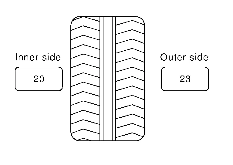
Calculation example:
23 g (0.81 oz) × 5/3 = 38.33 g (1.35 oz) ⇒ 37.5 g (1.32 oz) balance weight (closer to calculated balance weight value)
 NOTE:
NOTE:
Note that balance weight value must be closer to the calculated balance weight value.
Example:
36.2 ⇒ 35 g (1.23 oz)
36.3 ⇒ 37.5 g (1.32 oz)
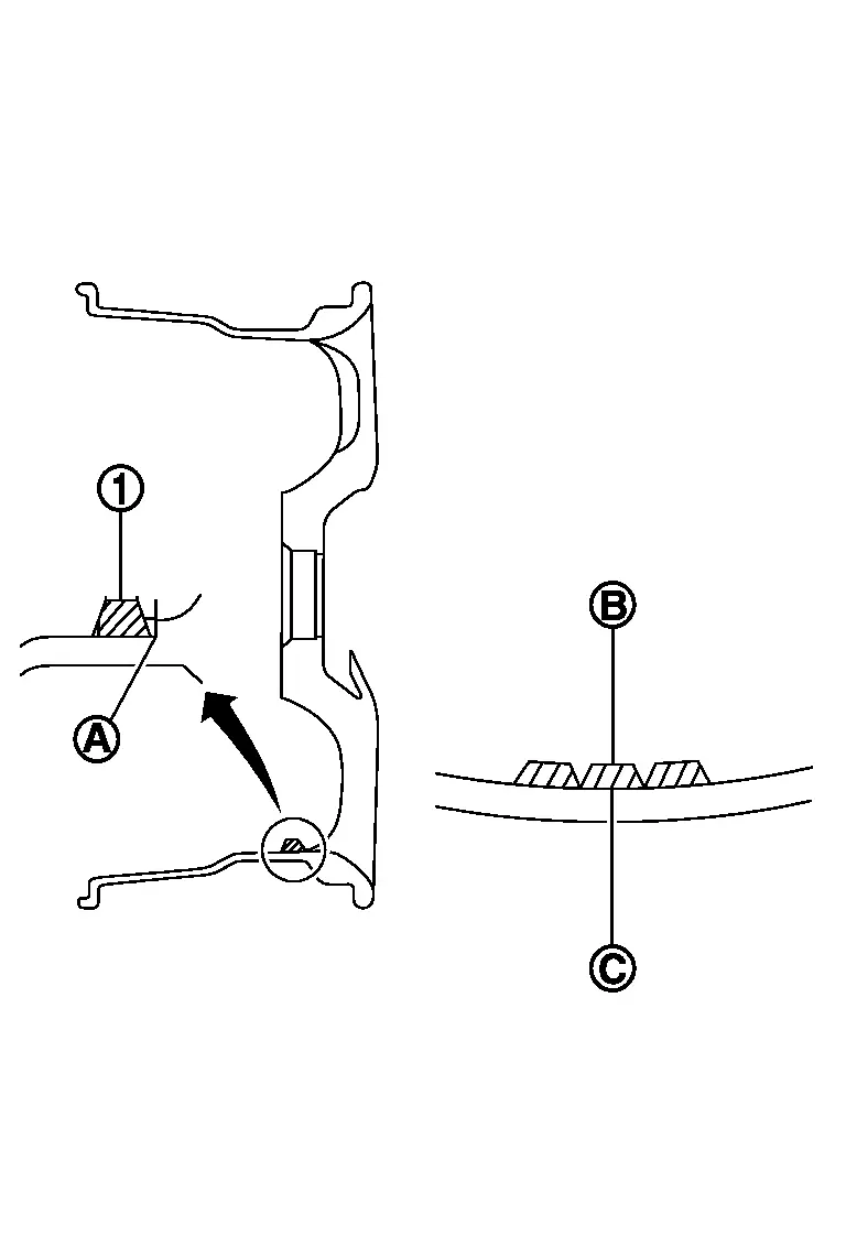
Installed balance weight in the position.When installing balance weight
 to road wheels, set it into the grooved area
  on the inner wall of the road wheel as shown in the figure so that the balance weight center
  is aligned with the tire balance machine indication position (angle)
  .
.
CAUTION:
Always use genuine NISSAN adhesion balance weights.
Balance weights are non-reusable; always replace with new ones.
Never install more than four sheets of balance weight.
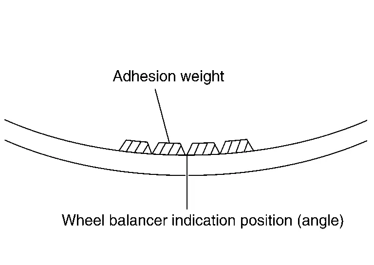
CAUTION:
Never install one balance weight sheet on top of another.
Start the tire balance machine again.
Install drive-in balance weight on inner side of road wheel in the tire balance machine indication position (angle).
CAUTION:
Never install more than two balance weight.
Start the tire balance machine. Check that the inner and outer residual unbalance value is within the allowable unbalance value.
CAUTION:
If either residual unbalance value exceeds limit, repeat installation procedures.
| Allowable unbalance value | |
| Dynamic (At flange) | : Refer to ROAD WHEEL : Service Data. |
| Static (At flange) | :Refer to ROAD WHEEL : Service Data. |
 Inspection
WARNING:
APPEARANCE
Road Wheel
Check road wheel for deformation, cracks, corrosion and other damage.
Check wheel nuts for looseness by using torque wrench.
Wheel nut tightening torque Refer to ROAD ...
 ROAD WHEEL TIRE : Rotation
WARNING:
Follow the maintenance schedule for tire rotation service intervals. Refer to General Maintenance.
When installing the wheel, tighten wheel nuts to the specified torque. Refer to ROAD WHEEL ...
Other materials:
Inspection and Adjustment
SYSTEM INITIALIZATION
Perform additional service for operating the power window control system normally after installing front door regulator. Refer to Work Procedure.
FITTING INSPECTION
Check that the glass is fitted securely into the sash groove.
Lower the glass slightly [approximately 10 to 20 m ...
Removal and Installation
CAUTION:
Never bend the pawl of power window switch finisher.
REMOVAL
Remove power window switch finisher (driver side). Refer to Removal & Installation.
Disengage door lock and unlock switch (driver side) fixing pawls using a remover tool (A), and then remove door lock and unlock switch (driver ...
Removal and Installation
WARNING:
REMOVAL
Disconnect battery cable from negative terminal. Refer to Removal and Installation.
Remove engine under cover rear. Refer to Removal and Installation.
Remove front cross member. Refer to Removal and Installation.
Remove starter motor cover 2 mounting bolts , and then remove starter ...

0.0066