Exploded View
WITHOUT WELDING TYPE
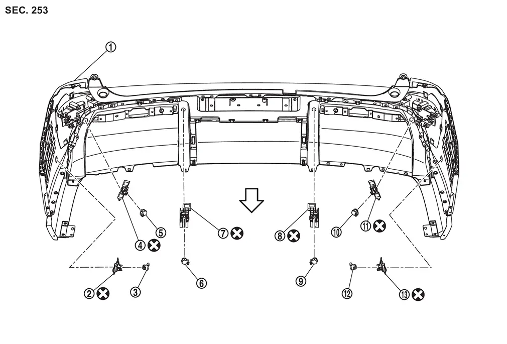
 |
Rear bumper fascia |  |
Side sensor rear RH holder |  |
Side sensor rear RH |
 |
Corner sensor rear RH holder |  |
Corner sensor rear RH |  |
Center sensor rear RH |
 |
Center sensor rear RH holder |  |
Center sensor rear LH holder |  |
Center sensor rear LH |
 |
Corner sensor rear LH |  |
Corner sensor rear LH holder |  |
Side sensor rear LH |
 |
Side sensor rear LH holder | ||||
 |
:Always replace after every disassembly. | ||||
| vehicle front | |||||
WITH WELDING TYPE
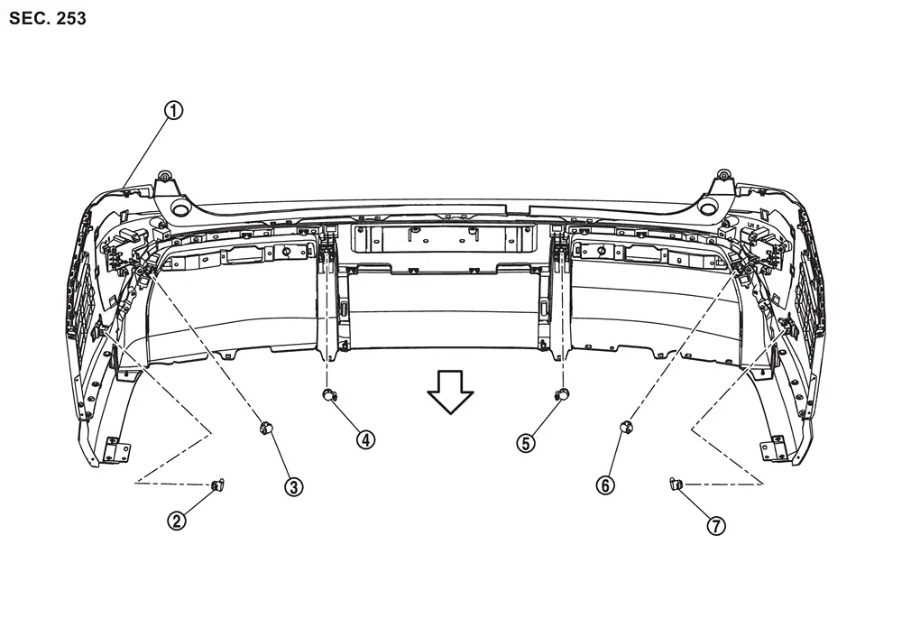
|
Rear bumper fascia | |
Side sensor rear RH | |
Corner sensor rear RH |
|
Center sensor rear RH | |
Center sensor rear LH | |
Corner sensor rear LH |
|
Side sensor rear LH | ||||
| vehicle front | |||||
Removal & Installation
WARNING:
-
Jacking up or lift up the vehicle may the vehicle height to go down which cause a personal injury and/or damage to the air suspension component parts. Refer to Precaution for when Jacking and Lifting Up the vehicle with Electronic Air Suspension System.
REMOVAL
Center sensor
 NOTE:
NOTE:
When removing the sensor holder, remove the rear bumper. Refer to Removal and Installation
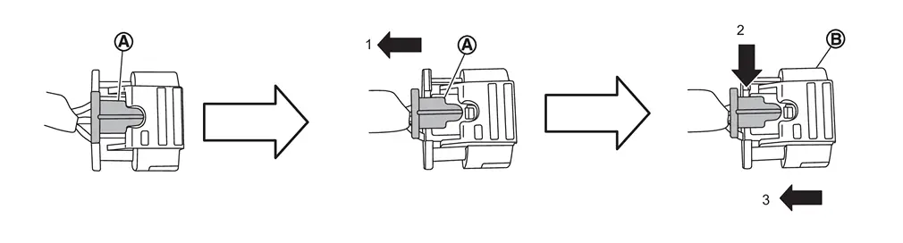
Disconnect sonar sensor harness connector , follow the procedure below.Slide the lock  of the connector toward the direction (1). Keep pushing (2) in the lock of connector and remove the harness connector
  to ward the direction (3).
Unhook the pawls in the direction ( ) and remove the sonar sensor from the sensor holder.
Remove the sensor holder from the rear bumper fascia. (Without welding type)
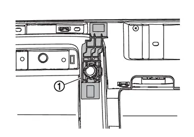
Corner sensor
NOTE:
When removing the sensor holder, remove the rear bumper. Refer to Removal and Installation
Disconnect sonar sensor harness connector , follow the procedure below.Slide the lock of the connector toward the direction (1). Keep pushing (2) in the lock of connector and remove the harness connector to ward the direction (3).
Unhook the pawls in the direction () and remove the sonar sensor from the sensor holder.
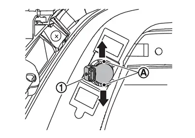
Remove the sensor holder from the rear bumper fascia. (Without welding type)
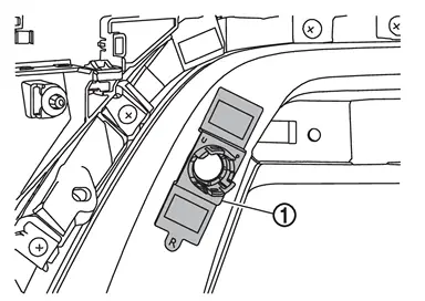
Side sensor
NOTE:
When removing the sensor holder, remove the rear bumper. Refer to Removal and Installation.
Disconnect sonar sensor harness connector , follow the procedure below.Slide the lock of the connector toward the direction (1). Keep pushing (2) in the lock of connector and remove the harness connector to ward the direction (3).
Unhook the pawls in the direction () and remove the sonar sensor from the sensor holder.
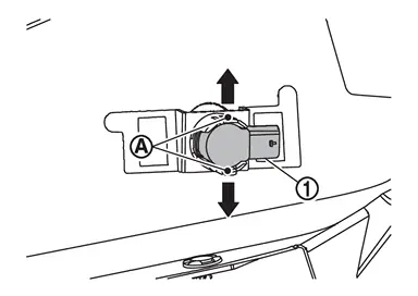
Remove the sensor holder from the rear bumper fascia. (Without welding type)
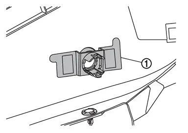
INSTALLATION
CAUTION:
-
Check sonar sensor packing for damage before installation.
-
Check that the packing is properly installed to the sonar sensor.
-
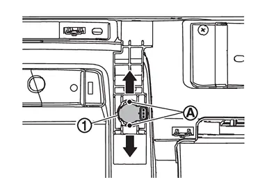
Install it so that the connector of the sensor turns to the arrow direction of the figure.
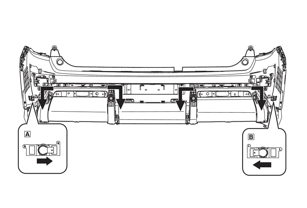

: Side sensor rear RH 
: Side sensor rear LH 
: Connector direction
Center sensor
Install in the reverse order of removal
-
Install in the reverse order of removal when install only the sensor.
-
Follow the procedure below when replace the sensor holder.
CAUTION:
Never reuse the sensor holder. Always use new sensor holder when removing and replacing sensor holder and/or rear bumper facia.
-
Hook the pawls
to install the sonar sensor to the sensor holder.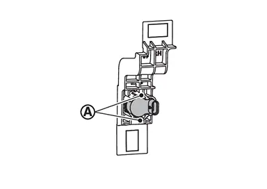
-
Degrease and clean the inner side of the bumper fascia base line
and then apply primer (3M K500,K520 or equivalent) on the sensor holder installing face , which is shown as on the figure.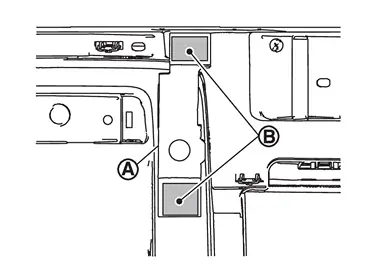
CAUTION:
Never apply two coats of primer. Applying two coats or more of primer results in excessively thick film and this may allow the sensor holder to come off from primer under exfoliation.
-
Dry the primer for more than 3 minutes and peel off the double sided tape releasing paper (film) and then taking precautions not to contact the bumper with the double sided tape (
on the figure), bend the sensor holder to the arrow direction as shown on the figure ().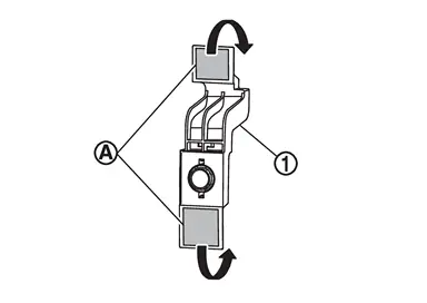
CAUTION:
Primer drying time depends on temperature and therefore confirm that primer has dried before bending the sonar holder.
-
Match the sonar sensor
part shown on the figure, to the sensor installing hole of the bumper fascia.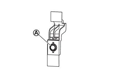
-
Remove the sensor from the sensor holder and press the adhesion face (
part on figure) throughout with your thumb for more than 2 seconds and pressure bond the sensor holder [Target pressure: 50 N (5.1kg, 11.3 lb)].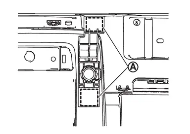
CAUTION:
-
When the temperature is less than 15°C (59°F), use a drier etc., to warm the adhesion face and proceed the work.
-
After installing the sensor holder, leave it at least for 2 - 3 hours.
-
-
Hook the pawls
to install the sonar sensor to the sensor holder.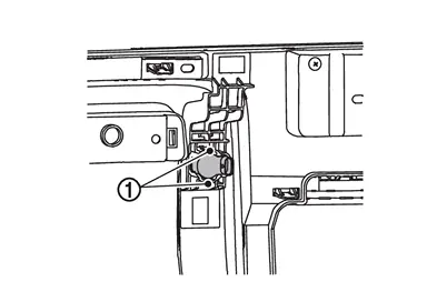
-
Shake the
part of the sensor holder shown on the figure up and down and then right and left to confirm that the holder has been installed (bonded) firmly. -
Connect connector to the sonar sensor.
-
Install the rear bumper. Refer to Removal and Installation.
Corner sensor
Install in the reverse order of removal
-
Install in the reverse order of removal when install only the sensor.
-
Follow the procedure below when replace the sensor holder.
CAUTION:
Never reuse the sensor holder. Always use new sensor holder when removing and replacing sensor holder and/or rear bumper facia.
-
Hook the pawls
to install the sonar sensor to the sensor holder.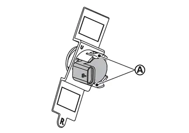
-
Degrease and clean the inner side of the bumper fascia base line
and then apply primer (3M K500,K520 or equivalent) on the sensor holder installing face , which is shown as on the figure.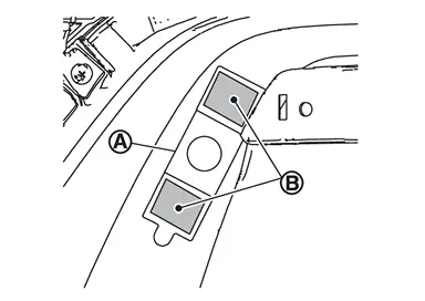
CAUTION:
Never apply two coats of primer. Applying two coats or more of primer results in excessively thick film and this may allow the sensor holder to come off from primer under exfoliation.
-
Dry the primer for more than 3 minutes and peel off the double sided tape releasing paper (film) and then taking precautions not to contact the bumper with the double sided tape (
on the figure), bend the sensor holder to the arrow direction as shown on the figure ().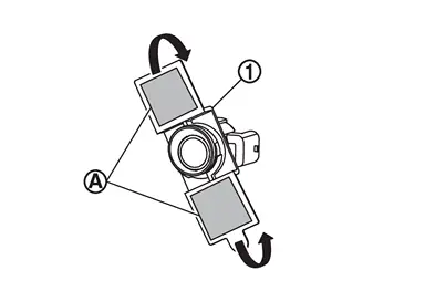
CAUTION:
Primer drying time depends on temperature and therefore confirm that primer has dried before bending the sonar holder.
-
Match the sonar sensor
part shown on the figure, to the sensor installing hole of the bumper fascia.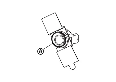
-
Remove the sensor from the sensor holder and press the adhesion face (
part on figure) throughout with your thumb for more than 2 seconds and pressure bond the sensor holder [Target pressure: 50 N (5.1kg, 11.3 lb)].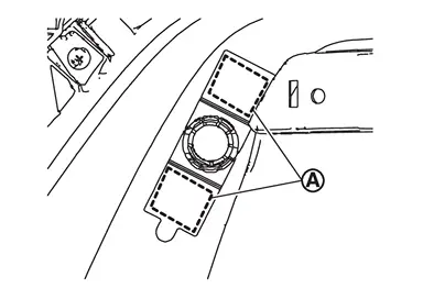
CAUTION:
-
When the temperature is less than 15°C (59°F), use a drier etc., to warm the adhesion face and proceed the work.
-
After installing the sensor holder, leave it at least for 2 - 3 hours.
-
-
Hook the pawls
to install the sonar sensor to the sensor holder.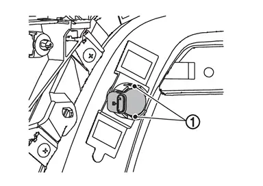
-
Shake the
part of the sensor holder shown on the figure up and down and then right and left to confirm that the holder has been installed (bonded) firmly. -
Connect connector to the sonar sensor.
-
Install the rear bumper. Refer to Removal and Installation.
Side sensor
WITH WELDING TYPE
Install in the reverse order of removal
WITHOUT WELDING TYPE
-
Install in the reverse order of removal when install only the sensor.
-
Follow the procedure below when replace the sensor holder.
CAUTION:
Never reuse the sensor holder. Always use new sensor holder when removing and replacing sensor holder and/or rear bumper facia.
-
Hook the pawls
to install the sonar sensor to the sensor holder.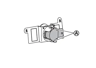
-
Degrease and clean the inner side of the bumper fascia base line
and then apply primer (3M K500,K520 or equivalent) on the sensor holder installing face , which is shown as on the figure.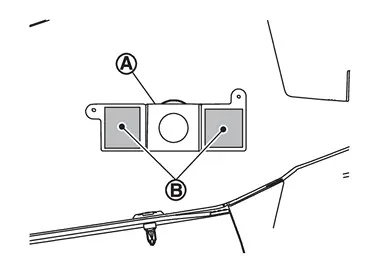
CAUTION:
Never apply two coats of primer. Applying two coats or more of primer results in excessively thick film and this may allow the sensor holder to come off from primer under exfoliation.
-
Dry the primer for more than 3 minutes and peel off the double sided tape releasing paper (film) and then taking precautions not to contact the bumper with the double sided tape (
on the figure), bend the sensor holder to the arrow direction as shown on the figure ().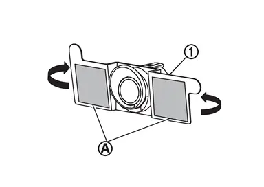
CAUTION:
Primer drying time depends on temperature and therefore confirm that primer has dried before bending the sonar holder.
-
Match the sonar sensor
part shown on the figure, to the sensor installing hole of the bumper fascia.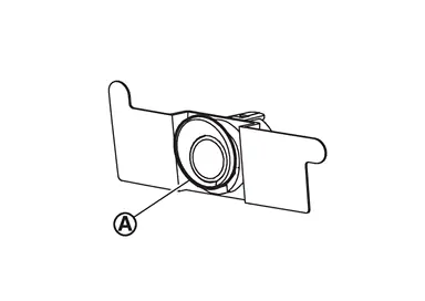
-
Remove the sensor from the sensor holder and press the adhesion face (
part on figure) throughout with your thumb for more than 2 seconds and pressure bond the sensor holder [Target pressure: 50 N (5.1kg, 11.3 lb)].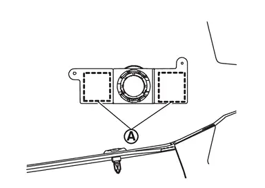
CAUTION:
-
When the temperature is less than 15°C (59°F), use a drier etc., to warm the adhesion face and proceed the work.
-
After installing the sensor holder, leave it at least for 2 - 3 hours.
-
-
Hook the pawls
to install the sonar sensor to the sensor holder.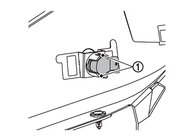
-
Shake the
part of the sensor holder shown on the figure up and down and then right and left to confirm that the holder has been installed (bonded) firmly. -
Connect connector to the sonar sensor.
-
Install the rear bumper. Refer to Removal and Installation.
Other materials
Safety note
WARNING
Never disassemble or modify the Nissan Armada system components. Doing
so may result in malfunction, fire, electric shock, or serious injury.
If the Nissan Armada system shows abnormal behavior, such as freezing,
loss of sound, or delayed response, discontinue use immediately.
...
Reservoir Tank Cap
Inspection
Check valve seat of reservoir tank cap.
: Metal plunger
Check if valve seat is swollen to the extent that the edge of the metal plunger cannot be seen when watching it vertically from the top.
Check if valve seat has no soil and damage.
Pull negative-pressure valve to ...
Automatic Back Door Warning Does Not Operate
Description
Automatic back door warning buzzer does not operate when automatic back door warning function are performed.
Diagnosis Procedure
CHECK AUTOMATIC BACK DOOR WARNING BUZZER
Check automatic back door warning buzzer.
Refer to DTC Diagnosis Procedure.
Is the inspection result normal?
YES>&g ...