Exploded View
WITHOUT ELECTRIC MOTOR
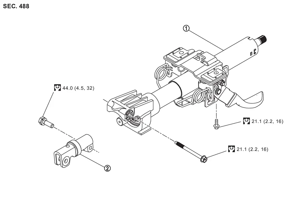
 |
Steering column assembly |  |
Upper joint | ||
 |
: N·m (kg-m, ft-lb) | ||||
WITH ELECTRIC MOTOR
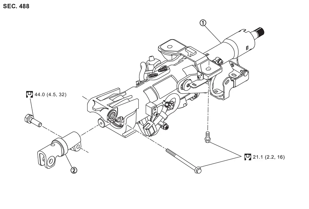
|
Steering column assembly | |
Upper joint | ||
|
: N·m (kg-m, ft-lb) | ||||
Removal and Installation
REMOVAL
CAUTION:
-
Never give axial impact to steering column assembly during removal.
-
Never move steering gear assembly when removing steering column assembly.
-
Never rotate the steering shaft when removing steering column assembly.
Set vehicle to the straight ahead position.
Place the tilt to the highest position. Place the telescopic to the middle position. (WITHOUT ELECTRIC MOTOR)
Place the tilt to the downest position. Place the telescopic to the longest position. (WITH ELECTRIC MOTOR)
Remove steering wheel. Refer to Removal and Installation.
Remove the cluster lid A. Refer to Removal and Installation.
Remove spiral cable. Refer to Removal and Installation.
Remove combination switch. Refer to Removal and Installation.
Remove driver knee air bag module. Refer to Removal and Installation.
Remove switch harness clips to braket (WITHOUT ELECTRIC MOTOR).
Disconnect each harness connectors installed to steering column assembly. (WITH ELECTRIC MOTOR).
Remove the upper joint fixing bolt  and nut
  (steering shaft side).
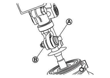
Separete the collar and steering shaft from upper joint  .
.
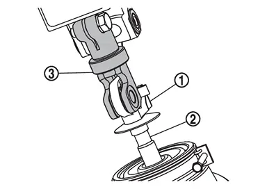
CAUTION:
When removing upper joint, never insert a tool, such as a screwdriver, into the yoke groove to pull out the upper joint. In case of the violation of the above, replace upper joint with a new one.
Remove the mounting bolts , and remove steering column assembly .
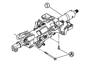
If necessary, remove upper joint and bolt from steering column assembly .
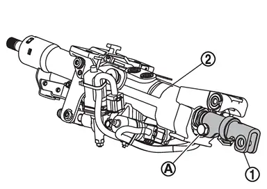
CAUTION:
-
Before removing the upper joint
from the steering column assembly , mark the mating part for alignment.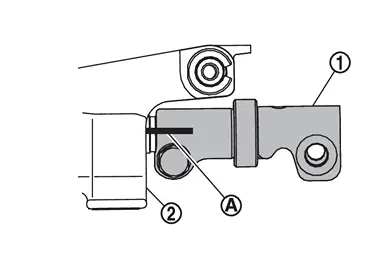
-
When removing upper joint, never insert a tool, such as a screwdriver, into the yoke groove to pull out the upper joint. In case of the violation of the above, replace upper joint with a new one.
Perform inspection after removal. Refer to Inspection.
INSTALLATION
Note the following, and install in the reverse order of removal.
CAUTION:
Never reuse steering shaft fixing bolt and nut.
-
When installing the steering column assembly, perform the following procedure.
-
Insert bolt
through the steering column hole.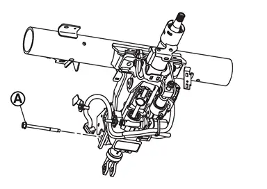
-
Temporary tighten the bolt with hand.
-
Insert bolts
through the steering column hole.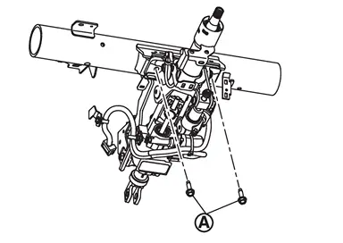
-
Temporary tighten the bolt with hand.
-
Tighten bolt
to the specified torque.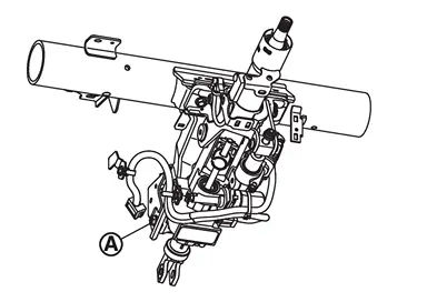
-
Tighten bolts
to the specified torque.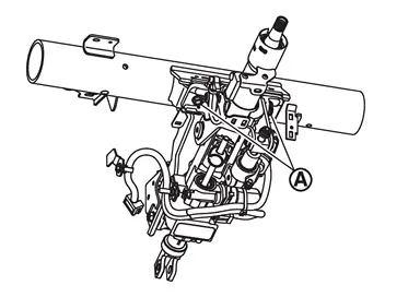
-
-
Be careful of the following points when installing the steering column assembly.
CAUTION:
-
Never give axial impact to steering column assembly during installation.
-
Never move steering gear assembly.
-
When replacing only the upper joint or steering column assembly with a new one, align the phase of the upper joint and steering column assembly so that the line mark stamped on the tip of the shaft of the steering column assembly faces straight up when the vehicle is traveling straight.
-
-
To install the upper joint
, align it with the matching marks on the steering column assembly put during the removal. -
Perform inspection after installation. Refer to Inspection.
Inspection
INSPECTION AFTER REMOVAL
Check the following items and replace, if necessary.
-
Check each part of steering column assembly for damage or other malfunctions. Replace if there are any abnormal conditions.
-
Measure steering column rotating torque using a preload gauge (commercial service tool) (A). Replace steering column assembly if the rotating torque is outside the standard.
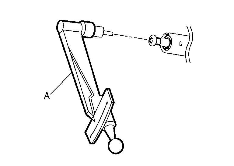
Rotating torque : Refer to Steering Column. -
With the column telescopic set to the longest position, measure the length (A) shown in the figure, if vehicle has been involved in a minor collision. Replace steering column assembly if out side the standard.
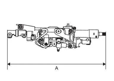
Steering column length [maximum telescopic (A)] : Refer to Steering Column. CAUTION:
-
Before completing this measurement, the steering column telescopic must be set to the longest position, the steering wheel will be nearest away from the driver.
-
If the column telescopic is not set to the longest position, first reinstall the column, move the telescopic to the longest position, then complete the measurement.
-
INSPECTION AFTER INSTALLATION
Check the following items and replace, if necessary.
-
Check each part of steering column assembly for damage or other malfunctions. Replace if there are any abnormal conditions.
-
Check tilt and telescopic mechanism operating range tilt operating range (A), telescopic operating range (B) as shown in the figure.
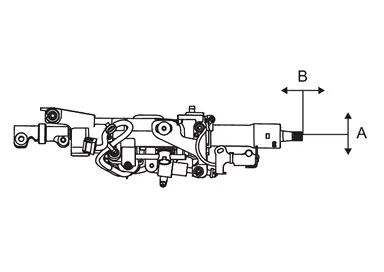
Tilt operating range (A) : Refer to Steering Column. Telescopic operating range (B) : Refer to Steering Column. -
After installation, turn steering wheel to make sure it moves smoothly while turning to the left and right stops.
-
Make sure that the steering wheel is in a neutral position when driving straight ahead.
-
Rotate steering wheel to check for decentered condition, binding, noise, or excessive steering effort.
-
Check the steering wheel play, neutral position steering wheel, steering wheel turning torque, and front wheel turning angle.
-
Steering wheel play: Refer to Inspection.
-
Neutral position steering wheel, steering wheel turning torque, and front wheel turning angle: Refer to Inspection.
-
-
Perform rack end value reset. Refer to Work Procedure.
-
Adjust neutral position of steering angle sensor. Refer to Work Procedure.
- If equipped with ProPILOT Assist, perform steering torque calibration after replacing or removal and installation the steering wheel. Refer to Work Procedure.
Other materials
Precautions
Precaution for Supplemental Restraint System (SRS) "AIR BAG" and "SEAT BELT PRE-TENSIONER"
The Supplemental Restraint System such as “AIR BAG” and “SEAT BELT PRE-TENSIONER”, used along with a front seat belt, helps to reduce the risk or severity of injury to the driver and front passenger fo ...
Fillet Molding
Exploded View
Front fillet molding
Rear fillet molding front
Rear fillet molding rear
Grommet
Double-sided tape
[t: 1.2 mm (0.047 in)]
: Clip
: Pawl
: vehicle front
: Always replace after every disassembly.
...
Roof Antenna
Exploded View
Roof antenna
: N·m (kg-m, in-lb)
Removal and Installation
REMOVALRemove the headlining assembly. Refer to Removal and Installation.
Disconnect the antenna feeder connector.
Remove the mounting nut.
Remove the roof antenna from the vehicle.INSTALLATIONNote the following, ...