
Nissan Armada 2025-2026 Service and Repair Manual: TIRE PRESSURE SENSOR : Removal & Installation
WARNING:
REMOVAL
Remove tire assembly. Refer to ROAD WHEEL TIRE : Removal & Installation.
Remove valve cap, valve core and then deflate tire.
 NOTE:
NOTE:
If the tire is reused, apply a matching mark to the position of the tire road wheel valve hole for the purpose of wheel balance adjustment after installation.
Use the tire changer and disengage the tire beads.
CAUTION:
Be sure not to damage the road wheel or tire pressure sensor.
Apply bead cream or an equivalent to the tire beads.
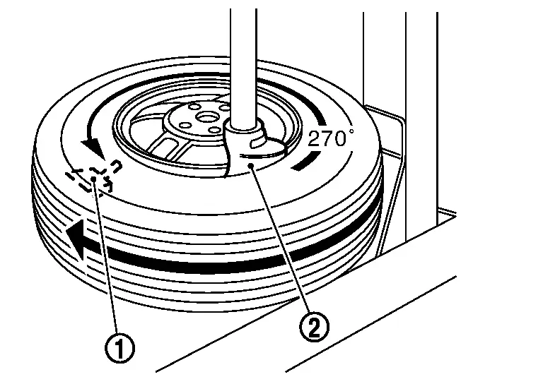
Turn tire so that valve hole is at bottom and bounce so that tire pressure sensor  is near valve hole. Carefully lift tire onto turntable and position valve hole (and tire pressure sensor) 270° from mounting/dismounting head
  .
.
CAUTION:
Be sure not to damage the road wheel and tire pressure sensor.
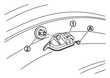
Remove mounting screw  , and then remove tire pressure sensor from valve .
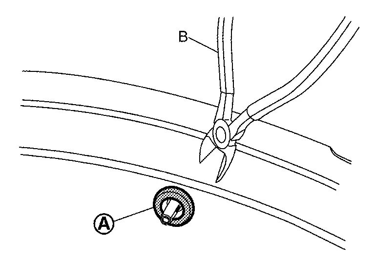
Cut the part of valve, using a pliers cutters (B).
CAUTION:
Be sure not to damage the road wheel.
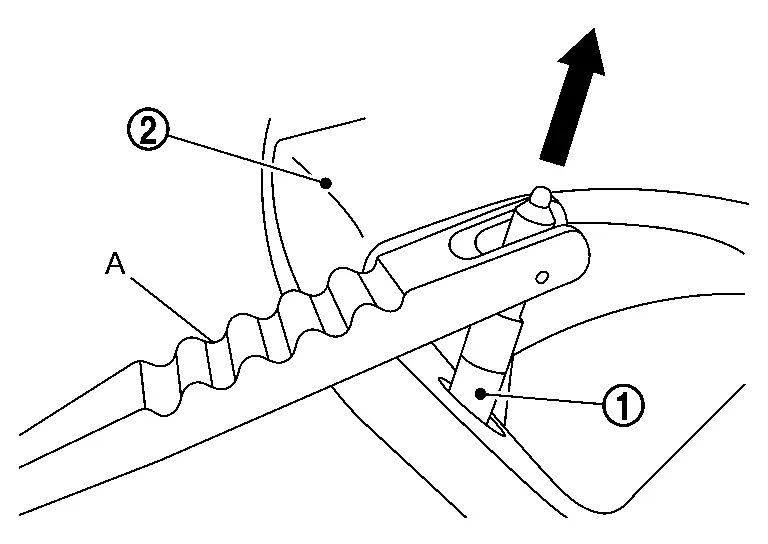
Remove the valve from road wheel , using a valve inserter (A).
CAUTION:
Be sure not to damage the road wheel.
Pull the valve straight through the rim hole perpendicularly to the rim hole.
INSTALLATION
CAUTION:
Never loosen the mounting screw if the tire pressure sensor and valve are assembled and spplied.
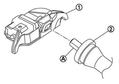
When reusing the tire pressure sensor, install the valve to the tire pressure sensor, follow the procedure below.Insert the tire pressure sensor to the roll pin of valve .
CAUTION:
Never reuse valve.
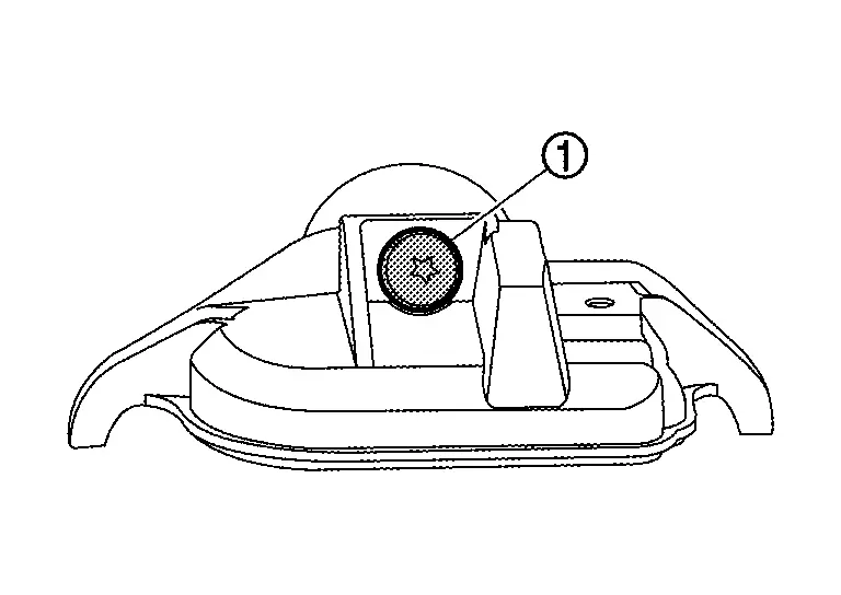
Install mounting screw.
CAUTION:
Never reuse mounting screw.
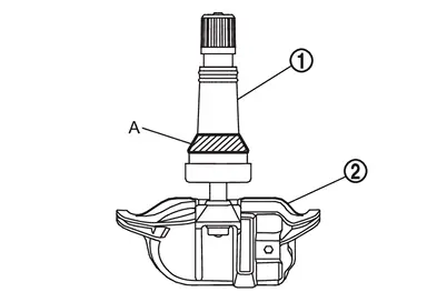
Apply a suitable non-silicone lubricant to the surface of the valve that touches (A) the wheel and to the valve hole in the wheel.
CAUTION:
Do not use silicone lubricant. Use of silicone lubricant will deteriorate the tire and wheel.
Do not allow lubricant to contact the tire pressure sensor
.
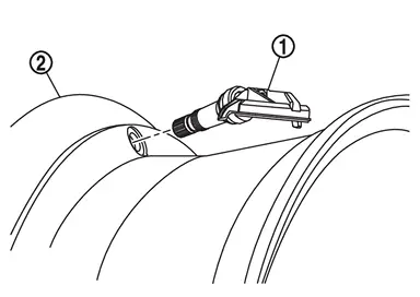
Install the tire pressure sensor assembly, follow the procedure below.Set the tire pressure sensor assembly to road wheel.
CAUTION:
Check the tire pressure sensor assembly direction, tire pressure sensor assembly must be inserted to the rim of road wheel as shown figure.
to road wheel , using a valve inserter (A).
CAUTION:
Be sure not to damage the road wheel.
Pull the valve straight through the rim hole perpendicularly to the rim hole.
Avoid any contact of the tire pressure sensor with the rim well and valve with the rim hole counter bore during insertion.
Insert tire pressure sensor assembly all the way to the road wheel.
Check that tire pressure sensor assembly contacts horizontally with road wheel.
Check the tire pressure sensor assembly
direction, tire pressure sensor assembly must be inserted to the rim of road wheel as shown figure.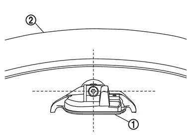
If the position is not correct, rotate the tire pressure sensor assembly to the correct position, using a valve inserter.
Apply bead cream or an equivalent to the tire beads.
Install the tire inside beads onto the road wheel in the position shown in the figure.
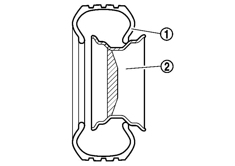
Set the tire onto the turntable so that the tire changer arm is at a position approximately 270° from the tire pressure sensor .
CAUTION:
Be sure that the arm does not contact the tire pressure sensor.
Install the tire outer side beads onto the road wheel.
CAUTION:
When installing, check that the tire does not turn together with the road wheel.
NOTE:
Before adding air, align the tire with the position of the matching mark applied at the time of removal.
Install tire to the vehicle. Refer to ROAD WHEEL TIRE : Removal & Installation.
Perform "TIRE PRESSURE SENSOR ID REGISTRATION" when tire pressure sensor is removed and installed, or replaced. Refer to Work Procedure.
 TIRE PRESSURE SENSOR : Exploded View
Screw Tire pressure sensor Valve Valve core Valve cap : N·m (kg-m, in-lb) : Always replace after every disassembly. : Parts that are replaced as a set when the tire is replaced. ...

Other materials:
Exploded View
Hood side seal Front fender drip cover Front fender bracket Front fender assembly Front fender protector tape Front fender duct Front fender baffle Fender cover LH Fender cover RH Double-sided tape [t: 0.8 mm (0.031 in)] : Clip : Pawl : Always replace after every disassembly : N·m (kg- ...
Special Service Tools
Tool number
(TechMate No.)
Tool name Description KV40104001
(NI-53385)
Hub lock nut wrench
a: 85 mm (3.35 in)
b: 65 mm (2.56 in)
Removing and Installing wheel hub lock nut. KV40107300
(NI-51751)
Boot band crimping tool
Installing boot band KV38108000
( - )
Protector
a: 47 mm (1.85 in) dia.
b: ...
GENERAL PRECAUTION : Precautions
WARNING:
When replacing fuel line parts, be sure to observe the following.
Put a “CAUTION: FLAMMABLE� sign in the workshop.
CAUTION:
Use gasoline required by the regulations for octane number.Refer to Fuel..
Before removing fuel line parts, perform out the following procedures:
Put drained fuel ...

0.0055