
Nissan Armada 2025-2026 Service and Repair Manual: Work Procedure
Always adjust the camera aiming after removing and installing or replacing the front camera unit.
Always adjust the camera aiming after removing and installing or replacing the windshield glass.
CAUTION:
Place the vehicle on level ground when the camera aiming adjustment is operated.
Be sure to place the target correctly according to work procedures because the system may not operate normally.
Follow the CONSULT when performing the camera aiming. (Camera aiming adjustment cannot be operated without CONSULT.)
Preparation
PERFORM SELF-DIAGNOSIS
Perform self-diagnosis of front camera unit.
Is any DTC detected?
YES>> NO>>GO TO 2.
PREPARATION BEFORE CAMERA AIMING ADJUSTMENT
Perform pre-inspection for diagnosis.
Adjust the tire pressure to the specified pressure value.
Maintain no-load in vehicle.
Check if coolant and engine oil are filled up to correct level and fuel tank is full.
Set shift position “P” position and release the parking brake.
Clean the windshield.
Completely clear off the instrument panel.
 NOTE:
NOTE:If any fixed object is put on instrument panel, cover the upper of the instrument panel with black cloth to prevent an object from reflecting in the windshield.
GO TO 3.
PREPARATION OF AIMING ADJUSTMENT JIG
Prepare the aiming adjustment jig according to the following procedure and the figure.
Prepare six sheets of white paper and black paper, respectively, with dimensions of 120 mm (4.72 in) × 120 mm (4.72 in) to create a left target and right target.
NOTE:Correct the magnification of print and print the target mark sample in the service manual on the black paper.
Tape three sheets of black paper and three sheets of white paper together to make a target of 360 mm (14.17 in) × 240 mm (9.45 in).
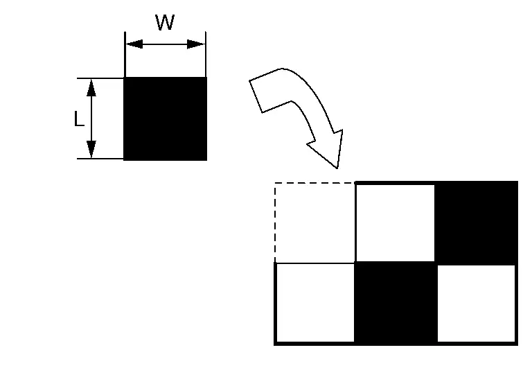
L : 120 mm (4.72 in) W : 120 mm (4.72 in) NOTE:Use a transparent tape.
Never apply tape to target surface.
Never allow a clearance on the black and white boundary.
Stick a printed target mark on the board with a scotch tape or a piece of double-sided tape.
NOTE:Use the board that peripheral area of the target is monochrome such as a white-board.
Notice that the cross of the target is horizontal and vertical.
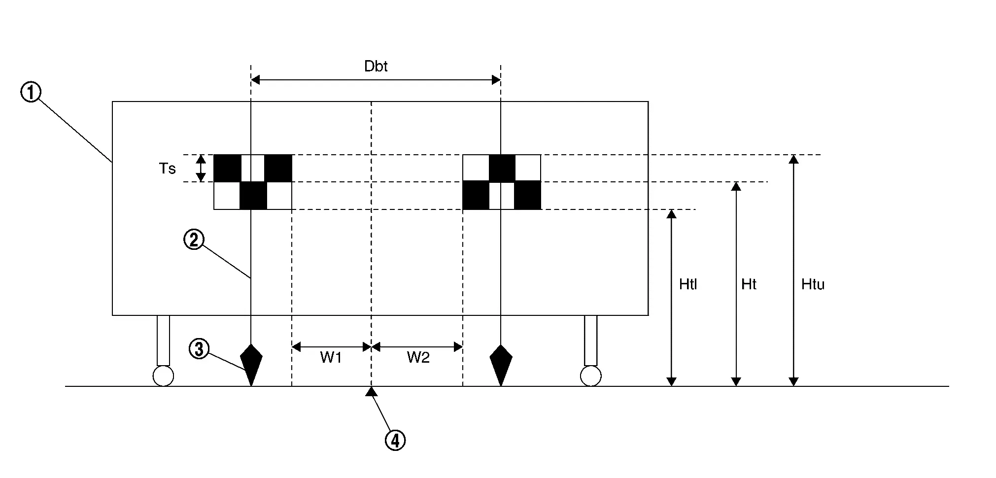

White wall 
String 
Cone 
Center between two targets Side of a target (Ts) : 120 mm (4.72 in) Height of a target lower end (Htl) : 1,180 mm (46.46 in) Height of a target center (Ht) : 1,300 mm (51.18 in) Height of a target upper end (Htu) : 1,420 mm (55.91 in) Width between a right target center from a left target center (Dbt) : 720 mm (28.35 in) W1 : 180 mm (7.09 in) W2 : 180 mm (7.09 in)
Proceed to Target Setting.
Target Setting
CAUTION:
Be sure to place the target correctly according to work procedures because the system may not operate normally.
Perform this operation in a horizontal position where there is a clear view for 5 m (16.4 ft) forward and 3 m (9.84 ft) wide.
Place the target in a well-lighted location. (Poor lighting may make it hard to adjust.)
The target may not be detected when there is a light source within 1.5 m (4.92 ft) from either side and within 1 m (3.28 ft) upward/downward from the target.
Check the location of the sun. (Sunlight should not shine directly on the front of the vehicle.)
The target may not be detected when there is the same pattern of black and white as the target when the pattern is within 1 m (3.28 ft) from either side and upward/downward position from the target. (It is desirable that the vehicle is positioned on the opposite side of a single-color wall.)
TARGET SETTING
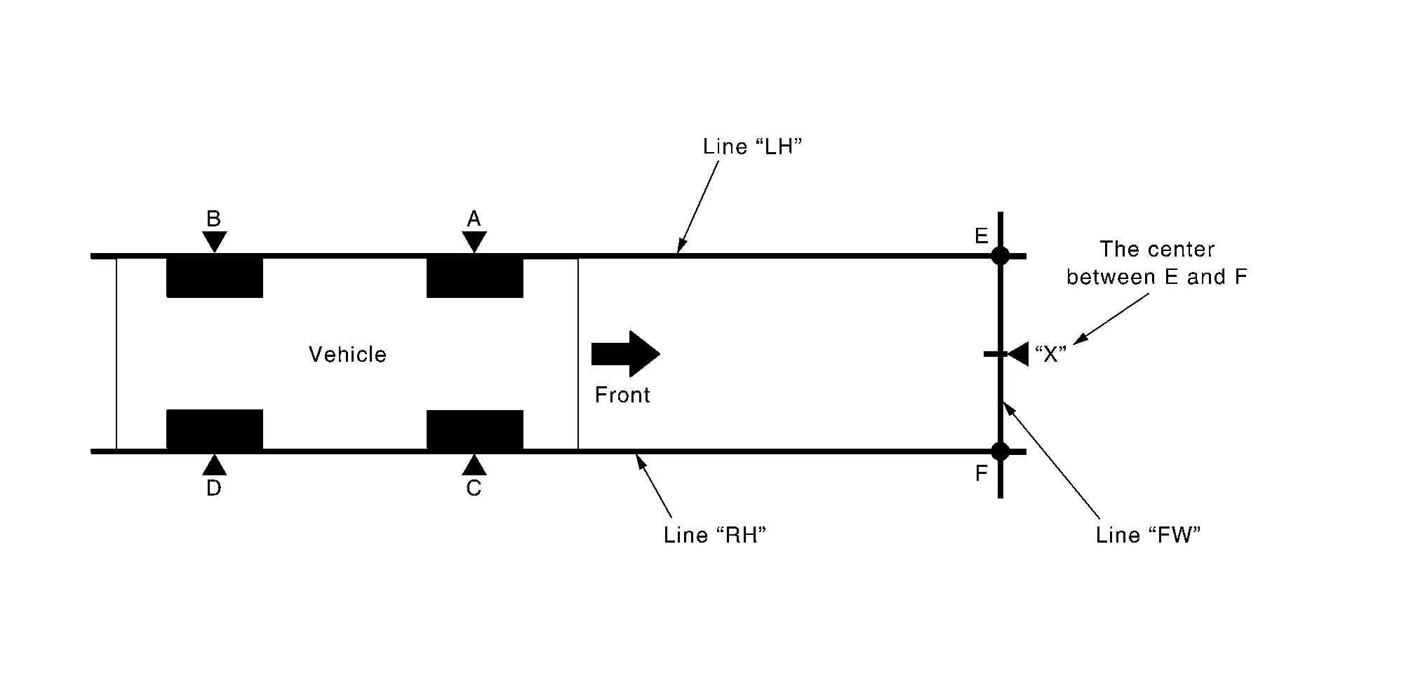
| A – E (C – F) | : 3,000 mm (118.11 in) |
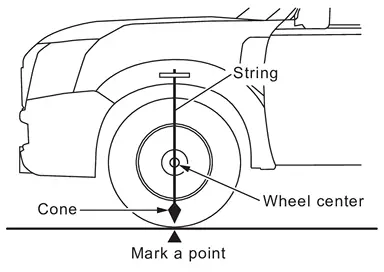
Mark points “A”, “B”, “C” and “D”at the center of the lateral surface of each wheels.
 NOTE:
NOTE:Hang a string with a cone from the fender so as to pass through the center of wheel, and then mark a point at the center of the lateral surface of the wheel.
Draw line “LH” passing through points “A” and “B” on the left side of vehicle.
NOTE:Approximately 4 m (13.12 ft) or more from the front end of vehicle.
Mark point “E” on the line “LH” at the positions 3,000 mm (118.11 in) from point “A”.
Draw line “RH” passing through points “C” and “D” on the right side of vehicle in the same way as step 2.
NOTE:Approximately 4 m (13.12 ft) or more from the front end of vehicle.
Mark point “F” on the line “RH” at the positions 3,000 mm (118.11 in) from point “C”.
Draw line “FW” passing through the points “E” and “F” on the front side of vehicle.
Mark point “X” at the center of point “E” and “F” on the line “FW”.
CAUTION:
Make sure that “E” to “X” is equal to “F” to “X”.
Place a target on either side of point “X”. Each distance from point “X” must be equal each other.
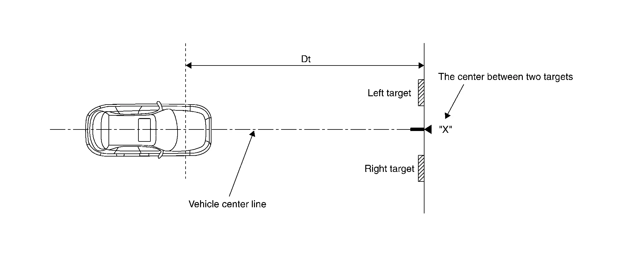
Dt : 3,000 mm (118.11 in)
Proceed to Camera Aiming Adjustment.
Camera Aiming Adjustment
CAUTION:
Perform the adjustment under unloaded vehicle condition.
CHECK VEHICLE HEIGHT
Measure the wheelarch height.
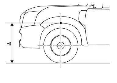
| Hfl: Front left wheelarch height [mm] | |
| Hfr: Front right wheelarch height [mm] | |
CAUTION:
Be sure to measure wheelarch height correctly.
>>GO TO 2.
CAMERA AIMING ADJUSTMENT
 With CONSULT
CAUTION:
Operate CONSULT outside the vehicle, and close all the doors. (To retain vehicle attitude appropriately)
Select “Work Support” on “LANE CAMERA” with CONSULT.
Select “AUTO AIM”.
Confirm the following items;
The target should be accurately placed.
The vehicle should be stopped.
Select “Start” to perform camera aiming.
CAUTION:
Never select “Start” when the target is not accurately placed.
Wait 5 seconds or more after selecting “Start”.
Input the following parameters, and then select “Start”.
Hfl : Measured value Hfr : Measured value Vehicle Reference Value : 789 VP : 0 Dt : 3,000 mm Dbt : 720 mm Htu : 1,420 mm Htl : 1,180 mm Ts : 120 mm Confirm the displayed item.
“Normally Completed”: Select “Completion”.
NOTE:When normally completed , code "0" is displayed.
"Suspension" or "Abnormally completed": Select "Completion", perform the following services.
Displayed item Possible cause Service procedure Abnormally completed 1 Internal processing error Check self-diagnosis result. If DTC is detected, perform trouble diagnosis.
Turn the ignition switch OFF→ON, then position the target appropriately again and perform camera aiming.
If abnormally completed even after aiming again, replace front camera unit.
2 3 4 Front camera unit malfunction If front camera unit is already replaced, perform C/U configuration again.
Turn the ignition switch OFF→ON, then accurately position the target again and perform camera aiming.
If abnormally completed even after aiming again, replace front camera unit.
5 Internal process time out Turn the ignition switch OFF→ON, then accurately position the target and perform camera aiming again.
If abnormally completed even after aiming again, replace front camera unit.
6 Ignition switch is not turned yet OFF→ON after replacing front camera unit. Turn the ignition switch OFF→ON, then position the target appropriately again and perform camera aiming. 7 Writing value malfunction If front camera unit is already replaced, perform configuration.
Position the target appropriately again. Then perform the aiming again.
If abnormally completed even after performing above procedure, replace front camera unit.
8 Position of front camera unit is not correct. Accurately position front camera unit.
Accurately position the target again, and perform camera aiming.
9 Camera aiming input value is invalid.
Input value is not correct during camera aiming.
Correct the camera aiming input value and perform camera aiming again. 16 Other error Check self-diagnosis result. If DTC is detected, perform trouble diagnosis.
Turn the ignition switch OFF→ON, then position the target appropriately again and perform camera aiming.
If abnormally completed even after aiming again, replace front camera unit.
18 Front camera unit cannot detect target
Target is not positioned
Position of front camera unit is not correct.
Inappropriate work environment.
Inappropriate vehicle condition
Input value is not correct during camera aiming.
Appropriately position the front camera unit.
Appropriately position the target again and perform camera aiming.
19 Roll angle is outside the threshold.
Position of front camera unit is not correct.
Inappropriate work environment.
Inappropriate vehicle condition.
Input value is not correct during camera aiming.
20 Front camera unit cannot detect the target. Perform front camera unit C/U configuration.
Check target setting information.
Position the target appropriately again. Then perform the aiming again.
21 Parameter read error Perform front camera unit C/U configuration.
Check target setting information and perform camera aiming.
22 "Dt" input value error Check target setting information and perform camera aiming. 23 "Ts" input value error 24 Yow angle is outside the threshold.
Position of target is not correct.
Position of front camera unit is not correct.
Inappropriate work environment.
Inappropriate vehicle condition.
Input value is not correct during camera aiming.
Appropriately position the front camera unit.
Appropriately position the target again and perform camera aiming.
25 Pitch angle is outside the threshold.
Position of target is not correct.
Position of front camera unit is not correct.
Inappropriate work environment.
Inappropriate vehicle condition.
Input value is not correct during camera aiming.
26 Detect several targets.
Position of target is not correct.
Position of front camera unit is not correct.
Inappropriate work environment.
Inappropriate vehicle condition.
Input value is not correct during camera aiming.
27 Aiming error Perform camera aiming again 28 Front camera unit cannot detect the left target Appropriately position the target again and perform camera aiming. 30 Front camera unit cannot detect the right target 31 Aiming error Perform camera aiming again 255 No aiming done Turn the ignition switch OFF→ON, then position the target appropriately again and perform camera aiming. NOTE:Replace front camera unit if “00H Routine not activated” or “10H Writing error” are repeatedly indicated during the above two services are performed.
Confirm that “Normally completed” is displayed and then select “End” to close the adjustment procedure.
GO TO 3.
PERFORM SELF-DIAGNOSIS
With CONSULT
Perform self-diagnosis of “LANE CAMERA” with CONSULT.
Is any DTC detected?
YES>> NO>>GO TO 4.
ACTION TEST
Perform the following system operation by action test.
LDW: Refer to Work Procedure.
I-LI: Refer to Work Procedure.
I-BSI: Refer to Work Procedure.
TSR: Refer to Work Procedure.
WORK END
TARGET MARK SAMPLE
NOTE:
Change the magnification of print to 120 mm (4.72 in) × 120 mm (4.72 in) and print the target mark sample.



Other materials:
Inspection
SIDE RADAR IRRADIATION AREA
For side radar irradiation area, refer to the figure below.
Rear bumper fascia Side radar irradiation area Reference point (R end) C 115 mm
(4.53 in) (vertical line) D 70 mm
(2.76 in) (vertical line) E 215 mm
(8.46 in) (horizontal line) F 105 mm
(4.13 in) (vertic ...
Exploded View
WITHOUT ELECTRIC MOTOR
Steering column assembly Upper joint : N·m (kg-m, ft-lb)
WITH ELECTRIC MOTOR
Steering column assembly Upper joint : N·m (kg-m, ft-lb) ...
Precautions for Removing Battery Terminal
NOTE:
NOTE:
NOTE:
The removal of 12V battery may cause a DTC detection error.
HOW TO DISCONNECT 12V BATTERY TERMINAL
Disconnect 12V battery terminal according to instruction described below.
Open the hood.
Turn ignition switch to the ON position.
Turn ignition switch to the OFF position with the d ...

0.0054