Exploded View
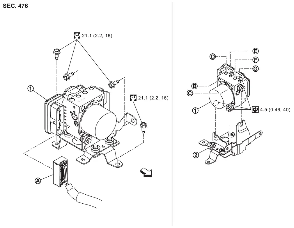
 |
ABS actuator and electric unit (control unit) |  |
Bracket | ||
 |
ABS actuator and electric unit (control unit) harness connector |  |
To electrical brake control unit primary side |  |
To electrical brake control unit secondary side |
 |
To front RH caliper |  |
To front LH caliper |  |
To rear RH caliper |
 |
To rear LH caliper | ||||
| : vehicle front | |||||
 |
: N·m (kg-m, ft-lb) | ||||
 |
: N·m (kg-m, in-lb) |
Removal and Installation
WARNING:
-
Jacking up or lift up the vehicle may the vehicle height to go down which cause a personal injury and/or damage to the air suspension component parts. Refer to Precaution for when Jacking and Lifting Up the vehicle with Electronic Air Suspension System.
REMOVAL
Disconnect the battery cable from negative terminal. Refer to Removal and Installation
Drain brake fluid. Refer to Draining.
Disconnect ABS actuator and electric unit (control unit) harness connector , follow the procedure below.
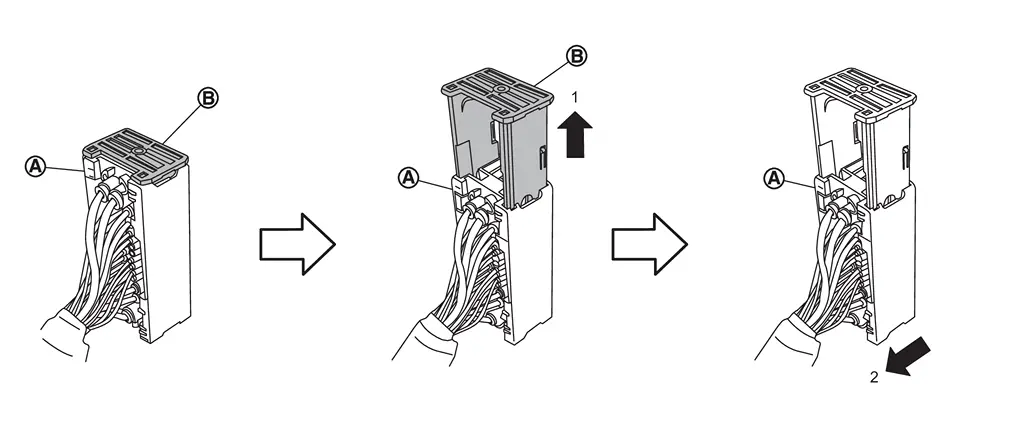
of the connector toward the direction (1). Disconnect ABS actuator and electric unit (control unit) harness connector toward the direction (2).
Loosen flare nut of brake tube using a flare nut wrench.
Remove brake tube between electrical brake control unit to ABS actuator and electric unit (control unit).
Remove ABS actuator and electric unit (control unit) mounting bolt, then remove ABS actuator and electric unit (control unit).
CAUTION:
-
Never remove and never install ABS actuator and electric unit (control unit) by holding harness connector.
-
Be careful not to drop ABS actuator and electric unit (control unit) and apply excessive impact to it.
Remove bracket from ABS actuator and electric unit (control unit).
INSTALLATION
Note the following, and install in the reverse order of removal.
-
When replacing ABS actuator and electric unit (control unit), remove the inlet hole protector for brake tube just before performing.
-
When installing brake tube, tighten to the specified torque using a flare nut torque wrench so that flare nut and brake tube are not damaged. Refer to Exploded View.
-
Never remove and install actuator by holding actuator harness.
-
Bleed air from brake piping after installation. Refer to Work Procedure.
-
Never apply excessive impact to actuator, such as by dropping it.
-
Install ABS actuator and electric unit (control unit) harness connector
, follow the procedure below.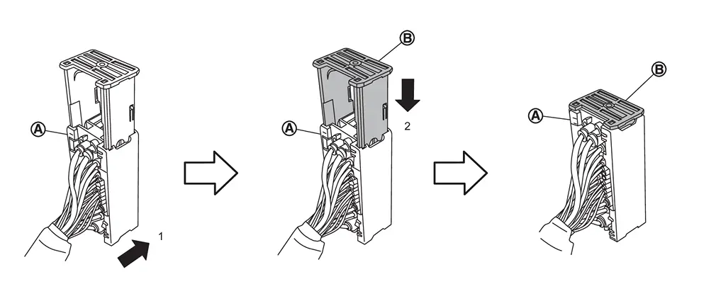
-
Install ABS actuator and electric unit (control unit) harness connector toward the direction (1).
-
Push the lock
of the connector toward the direction (2).
-
-
When replacing the ABS actuator and electric unit (control unit), perform "ADDITIONAL SERVICE WHEN REPLACING ABS ACTUATOR AND ELECTRIC UNIT (CONTROL UNIT)". Refer to Work Procedure.
Other materials
Transfer Range Position Sensor
Exploded View
Transfer assembly
Transfer range position sensor
: N·m (kg-m, in-lb)
Removal and Installation
WARNING:
Jacking up or lift up the vehicle may the vehicle height to go down which cause a personal injury and/or damage to the air sus ...
Differential Lock Position Switch
Exploded View
Rear final drive assembly
Differential lock position switch
O-ring
: N·m (kg-m, in-lb)
: Apply gear oil.
Removal and Installation
REMOVALIgnition switch OFF.
Disconnect negative battery terminal.
Disconnect the differential lo ...
Wireless Charger System Symptoms
Symptom Table
RELATED TO WIRELESS CHARGERMake sure the wireless charger is not in a deactivation condition before starting diagnosis. Refer to System Description. Symptoms Check items Possible malfunction location/Action to take
Wireless charging does not start
Ignition switch is not turned ON ...