Exploded View
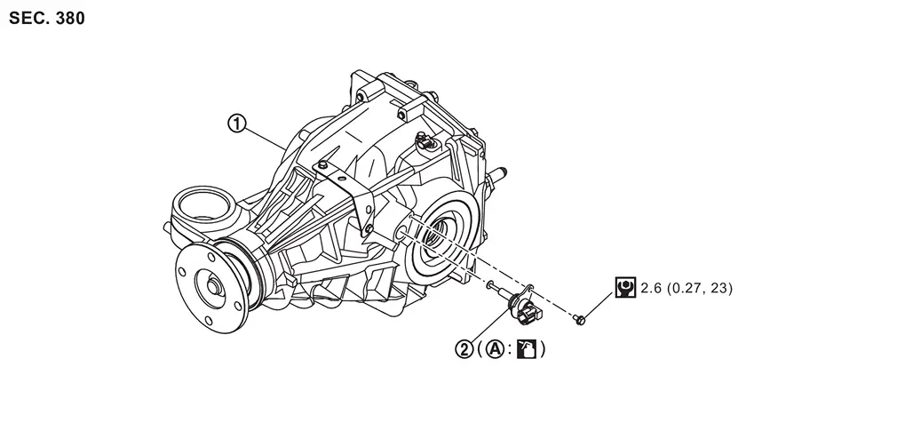
 |
Rear final drive assembly |  |
Differential lock position switch | ||
 |
O-ring | ||||
 : N·m (kg-m, in-lb) : N·m (kg-m, in-lb) |
|||||
 : Apply gear oil. : Apply gear oil. |
|||||
Removal and Installation
REMOVAL
Ignition switch OFF.
Disconnect negative battery terminal.
Disconnect the differential lock position switch harness connector.
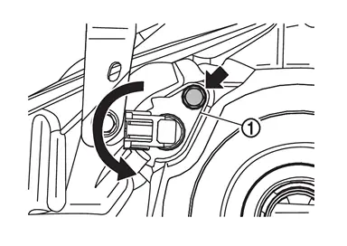
Remove differential lock position switch mounting bolt ( ) and remove differential lock position switch
  .
.
-
Rotate differential lock position switch counterclockwise then pull out to remove as shown.
INSTALLATION
Install in the reverse order of removal.
CAUTION:
-
Apply gear oil to the O-ring.
-
Never damage the O-ring of differential lock position switch.
-
Never contaminate or damage the O-ring mounting surface.
Other materials
Connecting Rod Bearings
Connecting Rod Bearing
DESCRIPTION Selection points Selection parts Selection items Selection methods
Between cylinder block and crankshaft
Main bearing
Main bearing grade
(bearing thickness)
Determined by match of cylinder block bearing housing grade (inner diameter of housing) and crank ...
Rear Axle Tools and Preparation
Special Service Tools
Tool number
(TechMate No.)
Tool name Description
KV40104001
(NI-53385)
Hub lock nut wrench
a: 85 mm (3.35 in)
b: 65 mm (2.56 in)
Removing and Installing wheel hub lock nut.
KV40107300
(NI-51751)
Boot band crimping tool
Installing boot band
KV38108000
( - )
...
Diagnosis and Repair Work Flow
Work Flow (With EXP-800 NI or GR8-1200 NI)
CHARGING SYSTEM DIAGNOSIS WITH EXP-800 NI OR GR8-1200 NITo test the charging system, use the following special service tools:
EXP-800 NI Battery and electrical diagnostic analyzer
GR8-1200 NI Multitasking battery and electrical diagnostic station
NOTE:
...