
Nissan Armada 2025-2026 Service and Repair Manual: Adjustment
PREPARATION BEFORE ADJUSTING
 NOTE:
NOTE:
For details, refer to the regulations in your own country.
Perform aiming if the vehicle front body has been repaired and/or the headlamp assembly has been replaced.
Before performing aiming adjustment, check the following.
Adjust the tire pressure to the specification.
Fill with fuel, coolant, and each oil.
Maintain the unloaded vehicle condition. (Remove luggage from the passenger compartment and the luggage room.)
NOTE:Never remove temporary tire, jack, and on-vehicle tool.
Wipe out dirt on the headlamp.
CAUTION:
Never use organic solvent (thinner, gasoline etc).
Ride alone on the driver seat.
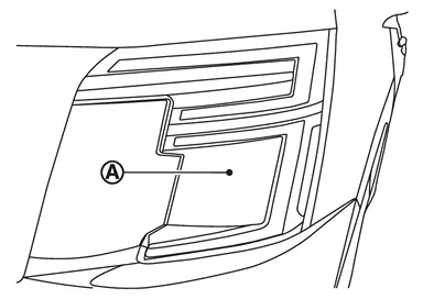
BULB CENTER WHEN ADJUSTING THE AIMING
When performing aiming adjustment, set headlamp (Lo) center at headlamp center mark  .
.
AIMING ADJUSTMENT SCREW
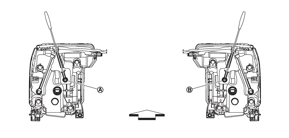
| Headlamp LH (UP/DOWN) adjustment screw |  | Headlamp RH (UP/DOWN) adjustment screw | ||
 | : Vehicle front | ||||
| Adjustment screw | Screwdriver rotation | Facing direction | |
|---|---|---|---|
| Headlamp LH (UP/DOWN) | Clockwise | UP |
| Counterclockwise | DOWN | ||
| Headlamp RH (UP/DOWN) | Clockwise | UP |
| Counterclockwise | DOWN | ||
AIMING ADJUSTMENT PROCEDURE
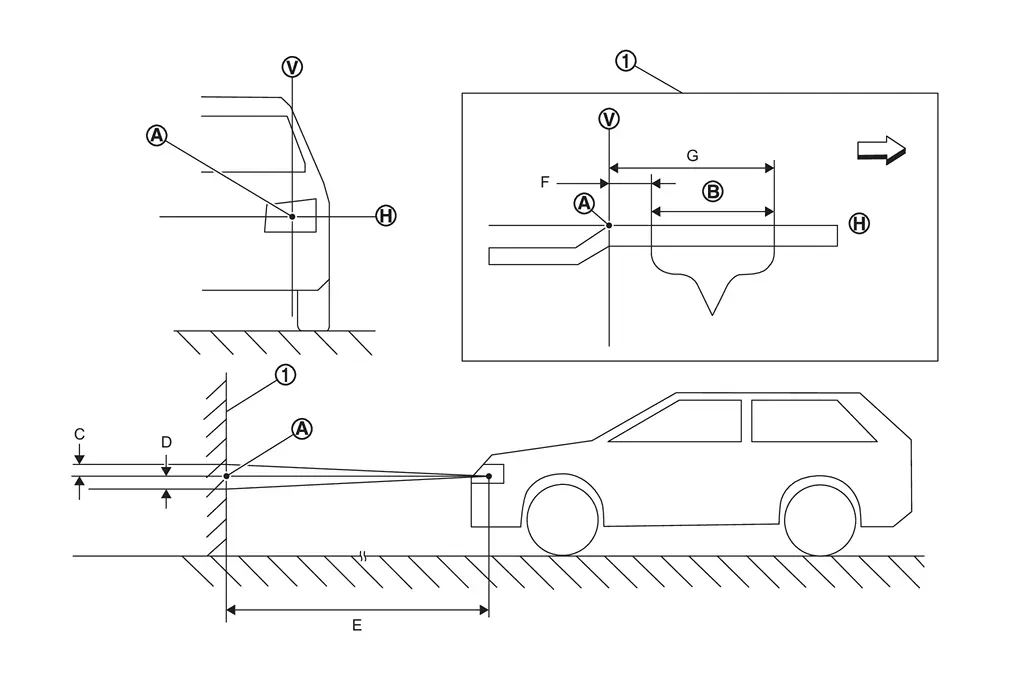
 | Adjustment screen | ||||
| Headlamp bulb center (H-V point) | | Aim evaluation area |  | Horizontal aiming evaluation line |
 | Vertical aiming evaluation line | ||||
| C | Highest cutoff line height | D | Lowest cutoff line height | E | Distance of headlamp adjustment screen from headlamp |
| F | Minimum aim evaluation distance from vertical center on adjustment screen 133 mm (1°R) | G | Maximum aim evaluation distance from vertical center on adjustment screen 399 mm (3°R) | ||
| : Vehicle right | ||||
| E | C | D | ||
|---|---|---|---|---|
| mm (in) | deg. | mm (in) | deg. | |
| 7.62 m (25 ft) | 23 mm (0.91 in) | 0.175° down | 43 mm (1.69 in) | 0.325° down |
| 10 m (32.8 ft) | 31 mm (1.22 in) | 0.175° down | 57 mm (2.24 in) | 0.325° down |
NOTE:
Basic illuminating area for evaluation and/or adjustment should be within range shown on aiming chart.
Use adjustment screw to perform aiming adjustment.
Ensure fog lamps are turned off (if equipped).
The vehicle should have its standard load, which may include any outfitting or other equipment. Any load that is normally carried in the vehicle should be in the vehicle while verifying or performing headlamp adjustment. Any other load should be removed.
Block the opposite headlamp from projecting a beam pattern onto the adjustment screen, using a suitable object. Aim each headlamp individually.
CAUTION:
Never cover the lens surface with a tape etc. The lens is made of resin.
Place the screen on the same level and flat surface as the vehicle.
NOTE:
Surface should be free of any debris that would cause a difference between the headlamp center and the adjustment screen.
Face the front of the vehicle to the screen and measure distance between the headlamp and the screen surface.
| Distance between the headlamp center and the screen | : 7.62 m (25 ft) or 10 m (32.8 ft) |
Start the engine. Turn the headlamp on.
Determine the preferred vertical aim range dimensions, using the aiming chart.
Measure the projected beam within the aim evaluation segment on the screen.
Adjust the beam pattern of each headlamp until the aim evaluation segment (the area relative to both the highest and lowest cutoff line height) is positioned within the vertical aim range dimensions shown on the aiming chart.


Other materials:
Frame Component Parts
2WD MODELS
Refer to parts catalogue for the replacement parts.
: Both sided anti-corrosive precoated steel sections
: High strength steel (HSS) sections
: Aluminum portion
No. Parts name Tensile
strength
(MPa) Both sided
anti-corrosive
precoated
steel sections Aluminum
portion Frame assembly ...
ENGINE COOLANT : Draining
WARNING:
WARNING:
To avoid being scalded, never change engine coolant when the engine is hot.
Wrap a thick cloth around reservoir tank cap and carefully remove reservoir tank cap.
First, turn reservoir tank cap a quarter of a turn to release built up pressure. Then turn reservoir tank cap all the wa ...
Locking with power door lock switch
Driver's armrest
Front passenger's armrest
Basic information
The Nissan Armada power door lock system allows centralized locking and unlocking
of all doors using switches located on both the driver’s and front passenger’s doors.
To lock all doors, press the switch to the lo ...

0.0055