Vr35ddtt
Exploded View
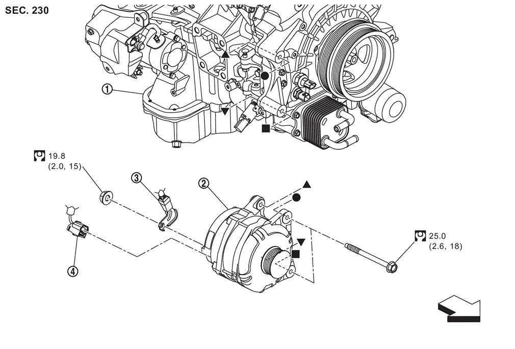
 |
Engine assembly |  |
Alternator |  |
“B� terminal harness |
 |
Alternator harness connector | ||||
| : vehicle front | |||||
 |
: N·m (kg-m, ft-lb) | ||||
 , , , ,  , ,  : Indicates that the part is connected at points with same symbol in actual vehicle. : Indicates that the part is connected at points with same symbol in actual vehicle. |
|||||
Removal and Installation
WARNING:
REMOVAL
Disconnect battery cable from negative terminal. Refer to Removal and Installation.
Remove drive belt. Refer to Removal & Installation.
Remove inlet air duct 2. Refer to Removal and Installation.
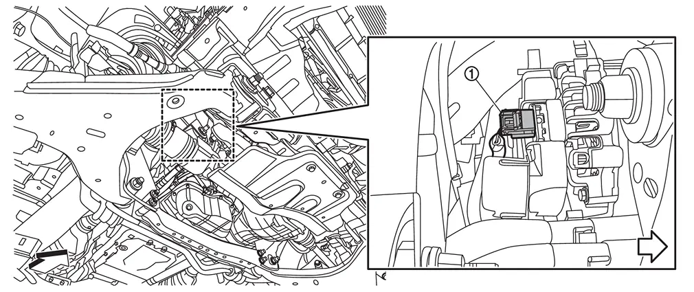
Disconnect alternator harness connector .
| : vehicle front |
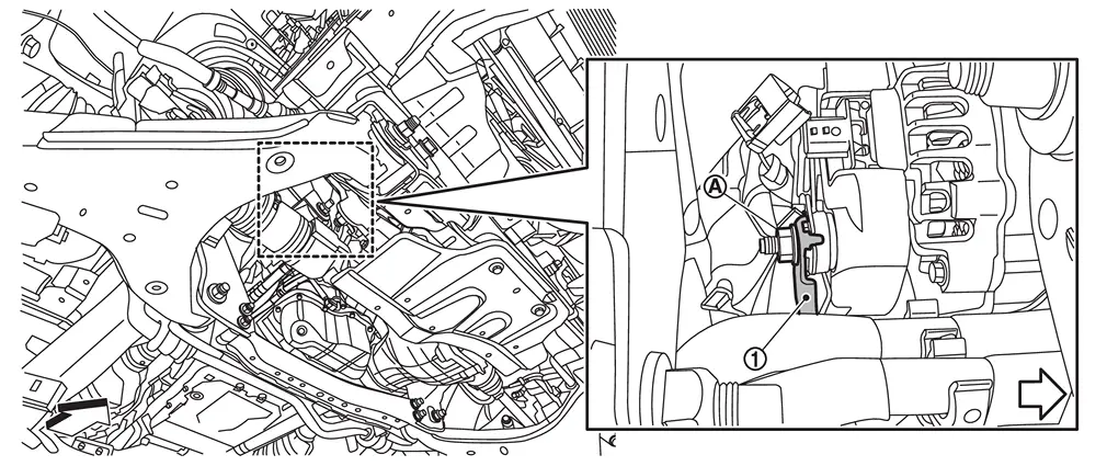
Remove “B� terminal harness mounting nut  , and then disconnect “B� terminal harness .
| : vehicle front |
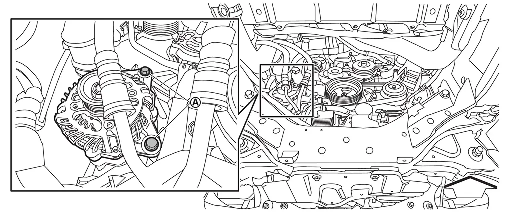
Remove alternator mounting bolts .
| : vehicle front |
Remove alternator from vehicle.
CAUTION:
Never damage around parts.
INSTALLATION
Note the following items, and then install in the reverse order of removal.
CAUTION:
-
Temporarily tighten alternator bolts in order from the lower side to the upper side, and then tighten them in order from the upper side to the lower side.
For alternator, the front side (pulley side) surface is the reference surface. Fit the reference surface to alternator mounting part, and then tighten bolts.
-
Be careful to tighten “B� terminal nut to the specified torque. Refer to Exploded View.
-
Install alternator, and check tension of drive belt. Refer to Inspection.
-
For this model (with 12V battery current sensor models), energy management system that controls power generation voltage of alternator has been adopted. Therefore, energy management system operation inspection should be performed after replacing alternator, and then make sure that the system operates normally. Refer to Work Flow (With EXP-800 NI or GR8-1200 NI) or Work Flow (Without EXP-800 NI and GR8-1200 NI).
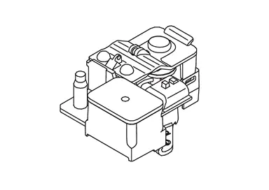
12V Battery current sensor is installed to 12V battery cable at negative terminal.
Other materials
Outside Key Antenna
Rear Door
Removal and Installation
REMOVALRemove rear door finisher. Refer to Removal & Installation.
Disconnect outside key antenna (rear door) harness connector.
Disengage outside key antenna (rear door) fixing clips, and then remove outside key antenna (rear door) .
: Clip
Disengage ...
Rear View Monitor
Symptom Table
REAR VIEW MONITOR Symptoms Possible cause Inspection item
Camera image is not shown.
(vehicle width and predictive course line are displayed.)
Harness between rear view camera and AV control unit
Rear view camera
AV control unit
Display unit
Perform “Self Diagnostic ...
Precautions
Precaution for Supplemental Restraint System (SRS) "AIR BAG" and "SEAT BELT PRE-TENSIONER"
The Supplemental Restraint System such as “AIR BAG� and “SEAT BELT PRE-TENSIONER�, used along with a front seat belt, helps to reduce the risk or severity of injury to the driver and front passenger fo ...