Exploded View
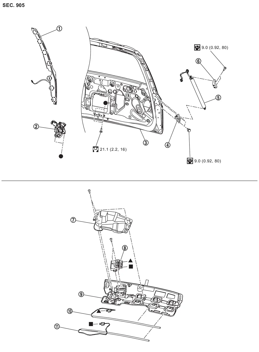
 |
Back door touch sensor*1 |  |
Back door lock & closure assembly |  |
Back door panel |
 |
Back door stay lower bracket |  |
Spindle unit*1 |  |
Spindle unit bracket upper*1 |
 |
Bracket cover*2 |  |
Hands free control unit*2 |  |
Hands free sensor bracket*2 |
 |
Hands free sensor upper*2 |  |
Hands free sensor lower*2 | ||
 |
: Clip | ||||
 |
: N·m (kg-m, in-lb) | ||||
 |
: N·m (kg-m, ft-lb) | ||||
 , , , ,  : Indicates that the part is connected at points with same symbol in actual vehicle. : Indicates that the part is connected at points with same symbol in actual vehicle. |
|||||
*1: With automatic back door models
*2: With hands free sensor models
Back Door Lock
Removal and Installation
REMOVAL
Remove back door inner finisher. Refer to Removal and Installation.
Disconnect back door lock & closure assembly harness connector.
Remove back door lock & closure assembly mounting bolts, and then remove back door lock & closure assembly from back door panel.
INSTALLATION
Note the following item, and then install in the reverse order of removal.
CAUTION:
After installation, check back door lock. Refer to Inspection.
Inspection
After opening and closing the back door, check that door is fixed to the vehicle body normally.
Check the lock/unlock operation of back door lock.
Check the back door lock lubrication condition. If necessary, apply body grease to back door lock.
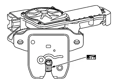
 |
: Body grease |
Unlock procedures
 NOTE:
NOTE:
Release lock according to the following procedures when lock cannot be unlocked due to a malfunction of back door lock or battery discharge.
Operated opener lever  of back door lock & closure assembly to unlock back door lock.
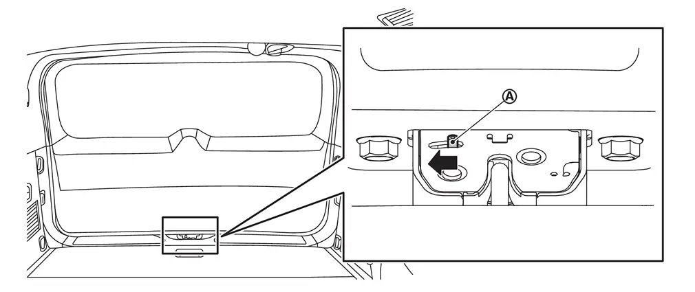
When lock cannot be unlocked operating opener lever, release lock according to the following procedures.Remove upper part of back door inner finisher to secure work space. Refer to Removal and Installation.
CAUTION:
Replace back door inner finisher when it is damaged.
Remove mounting bolts , and then remove back door lock actuator .
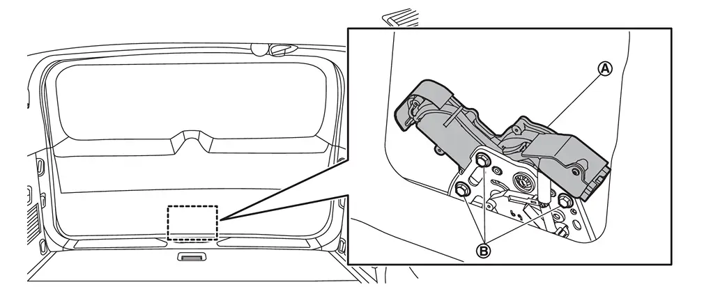
CAUTION:
When removing back door lock actuator, replace back door lock & closure assembly with a new one. Refer to Removal and Installation.
Operated opener lever of back door lock & closure assembly to unlock back door lock.Spindle Unit
Removal and Installation
CAUTION:
-
Perform work with 2 workers, because it is heavy weight.
-
Support back door with a proper material and use protective tape or shop cloth to protect back door and body from falling and damage when removing and installing spindle unit.
REMOVAL
Disconnect battery cable from 12V battery negative terminal. Refer to Removal and Installation.
Remove luggage side upper finisher LH. Refer to Removal and Installation.
Disconnect spindle unit harness connector .
-
LH side
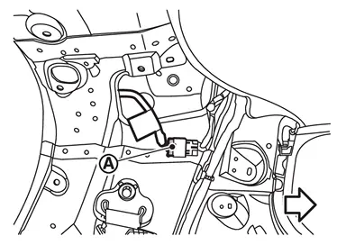
: vehicle front
-
RH side
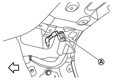
: vehicle front
Remove harness grommet from back main center pillar, and then pull out spindle unit harness from vehicle body.
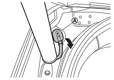
Support back door panel with a proper material to prevent it from falling.
WARNING:
Injury may occur if back door panel is not supported with appropriate material when removing back door assembly.
Remove metal clip located on connection between spindle unit and stud ball part of spindle unit bracket upper to using a remover tool (A) according to the numerical order 1→2 indicated by arrows as shown in figure.
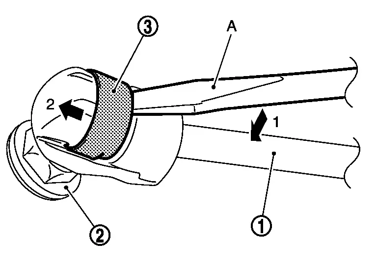
Disengage spindle unit from stud ball part of spindle unit bracket upper.
Repeat the same operation to disengage spindle unit from stud ball part of spindle unit bracket lower, and then remove spindle unit.
Remove spindle unit bracket upper mounting bolts, and then remove spindle unit bracket upper.
Remove back door touch sensor. Refer to Removal and Installation.
Remove spindle unit bracket lower mounting bolts, and then remove spindle unit bracket lower.
INSTALLATION
Note the following items, and then install in the reverse order of removal.
CAUTION:
-
When installation, check spindle unit harness connector
is inside the vehicle body pocket (RH side).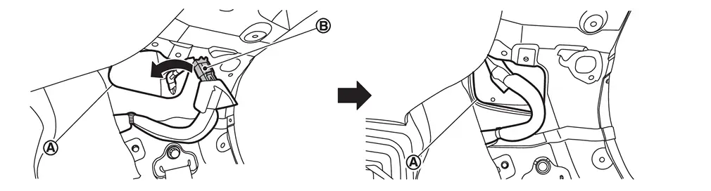
-
After installation, check back door lock. Refer to Inspection.
-
After installation, perform calibration of automatic back door position information. Refer to Work Procedure.
Back Door Touch Sensor
Removal and Installation
REMOVAL
Remove back door inner finisher. Refer to Removal and Installation.
Disconnect back door touch sensor harness connector .
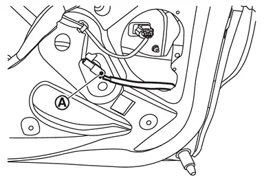
Remove back door touch sensor fixing clips.
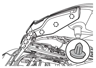
|
: Clip |
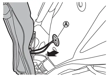
Remove harness grommet from back door panel, and then pull out back door touch sensor harness from back door panel and remove back door touch sensor.
INSTALLATION
Note the following items, and then install in the reverse order of removal.
CAUTION:
-
After installing, check that there is no clearance between back door touch sensor and back door panel.
-
After installation, check that back door turns over normally by back door touch sensor.
-
After installation, check door lock. Refer to Inspection.
Hands Free Control Unit
Removal and Installation
REMOVAL
Remove rear bumper fascia. Refer to Removal and Installation.
Remove bracket cover fixing screws, and then remove bracket cover.
Disconnect hands free sensor harness connectors.
Remove hands free control unit fixing screws, and then remove hands free control unit.
Remove hands free sensor upper and lower from hands free sensor bracket.
INSTALLATION
Note the following items, and then install in the reverse order of removal.
CAUTION:
-
After installation, check door lock. Refer to Inspection.
-
Never confuse hands free sensor upper (white harness) and hands free sensor lower (yellow harness).
-
After installation, check that automatic back door system by hands free function is activated in the detection area (with hands free sensor models). Refer to System Description.
Other materials
Main Bearing
Main Bearing
DESCRIPTION Selection points Selection parts Selection items Selection methods
Between cylinder block and crankshaft
Main bearing
Main bearing grade
(bearing thickness)
Determined by match of cylinder block bearing housing grade (inner diameter of housing) and crankshaft jour ...
Electric Power Steering Warning Lamp Does Not Turn Off
Description
Power steering warning lamp does not turn OFF several seconds after engine started.
Diagnosis Procedure
PERFORM SELF-DIAGNOSIS
With CONSULT
Perform self-diagnosis for “EPS/DIRECT ADAPTIVE STEERING 3�.
Is any DTC detected?
YES>>
Check the DTC. Refer to DTC Index.
NO>>
GO ...
Display Unit
Removal and Installation
REMOVALDisconnect the battery cable from the negative terminal.
Remove display unit display unit finisher RH and LH. Refer to Removal and Installation.
Remove display unit cover. Refer to Removal and Installation.
Remove the mounting screws of the display unit .
Pull the ...