Exploded View
Without ProPILOT ASSIST 2.1
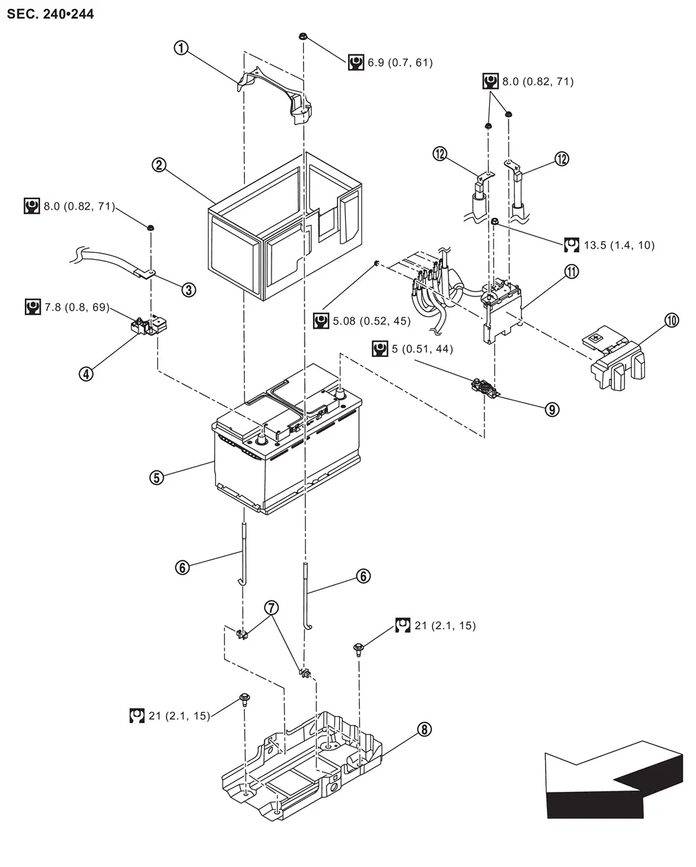
 |
Battery fix frame |  |
Battery cover |  |
Negative cable |
 |
Battery current sensor |  |
12V battery |  |
Battery fix rod |
 |
Battery fix rod clip |  |
Battery tray |  |
Battery positive terminal |
 |
Battery positive terminal cover |  |
Battery terminal with fusible link |  |
Positive cable |
 |
: N·m (kg-m, in-lb) | ||||
 |
: N·m (kg-m, ft-lb) | ||||
| : vehicle front |
With ProPILOT ASSIST 2.1
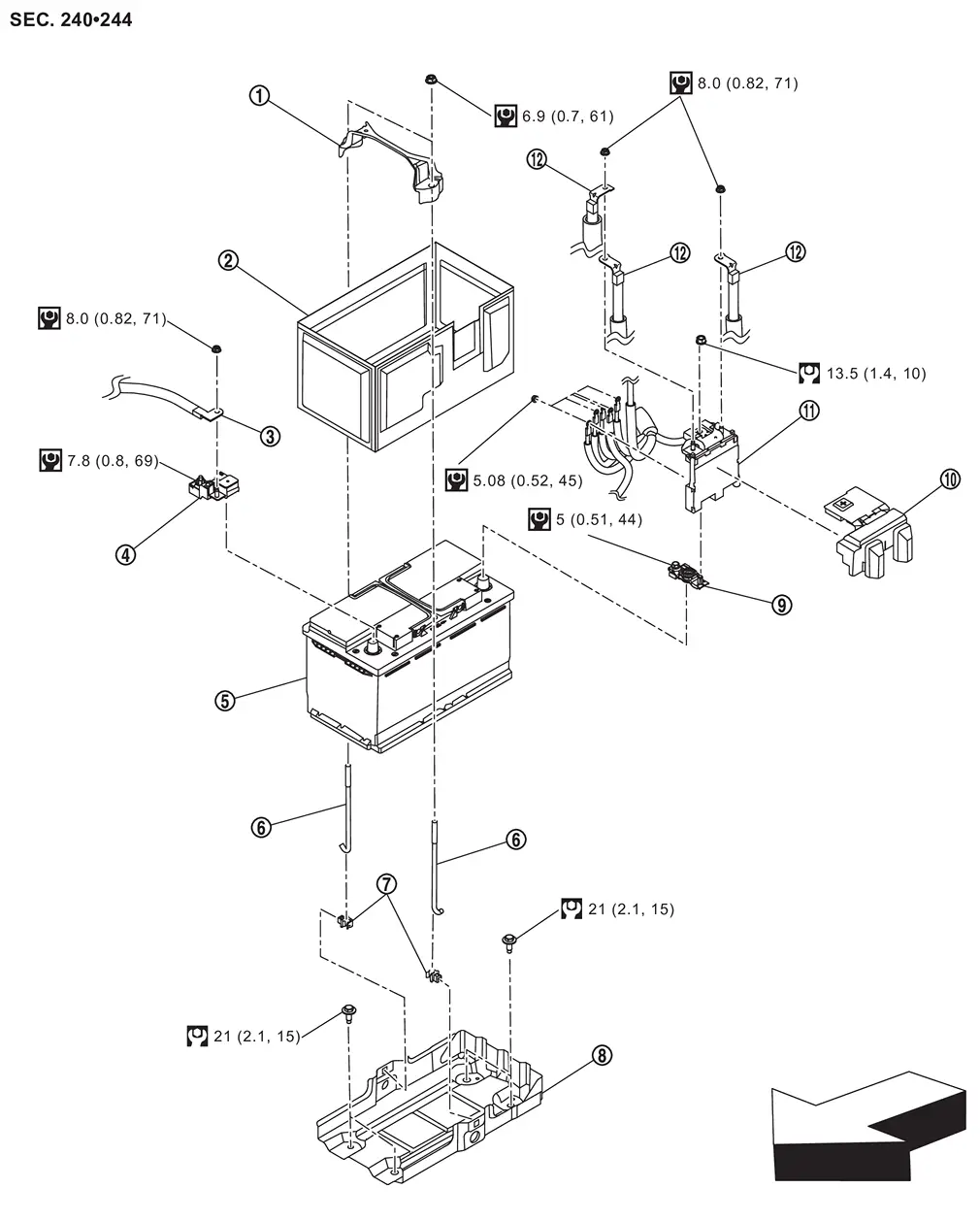
|
Battery fix frame | |
Battery cover | |
Negative cable |
|
Battery current sensor | |
12V battery | |
Battery fix rod |
|
Battery fix rod clip | |
Battery tray | |
Battery positive terminal |
|
Battery positive terminal cover | |
Battery terminal with fusible link | |
Positive cable |
|
: N·m (kg-m, in-lb) | ||||
|
: N·m (kg-m, ft-lb) | ||||
| : vehicle front |
Removal and Installation
REMOVAL
Disconnect the battery cable from the negative terminal. Refer to Exploded View.
CAUTION:
To prevent damage to the parts, disconnect the battery cable from the negative terminal first.
Remove the battery positive terminal cover.
Remove positive cable mounting nuts  , and then disconnect the positive cables
  from the battery terminal with fusible link .
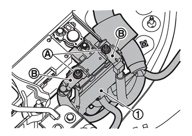
Remove battery terminal with fusible link mounting nut , and then remove the battery terminal with fusible link .

Remove cable mounting nuts , and then disconnect the cable ,  ,
,  ,
,  ,
,  and
and  from the battery terminal with fusible link .
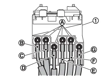
|
Red | |
Blue | |
Brown |
|
Green | |
White | |
Gray* |
| *: Without ProPILOT ASSIST 2.1 | |||||
INSTALLATION
Install in the reverse order of removal.
CAUTION:
-
To prevent damage to the parts, connect the battery cable to the positive terminal first.
-
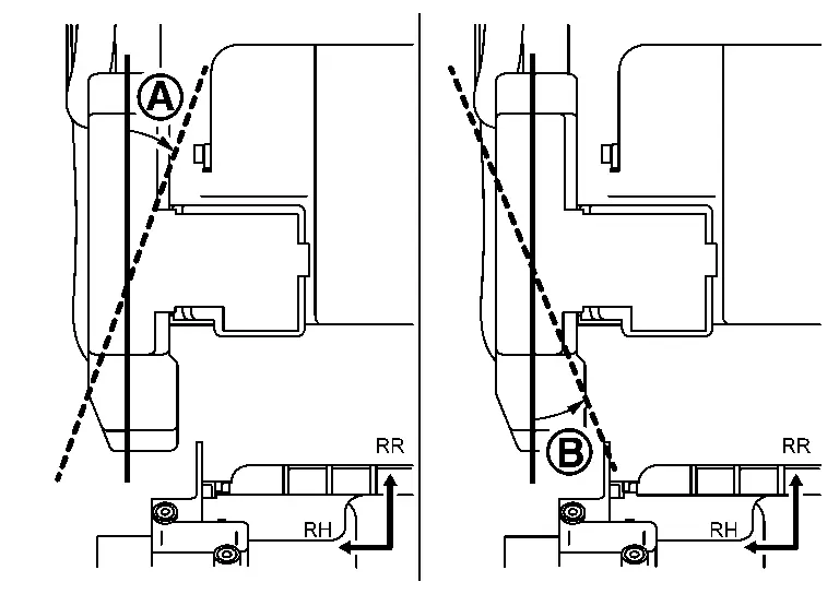
When installing battery terminal with fusible link cover, do not install it in the direction of
. Installing it in the direction of is acceptable.
Other materials
Turbocharger
Exploded View
Bank 1 side
Water inlet hose
Clamp
Water inlet tube
O-ring
Heat insulator (upper)
Oil return pipe 1
Oil return hose
Oil return pipe 2
Heat insulator (lower)
Water outlet tube
Turbocharger assembly
Gasket 1
Stud bolt
Oil feed tube
Eye bolt ...
Side Turn Signal Lamp
Exploded View
For exploded view of side turn signal lamp, refer to Exploded View.
Removal and Installation
CAUTION:
Disconnect the battery negative terminal or remove power circuit fuse when performing the operation for preventing electric leakage. Refer to Precautions for Removing Battery Terminal. ...
Axle and Suspension Parts
Inspection
Check front and rear axle and suspension parts for excessive play, cracks, wear or other damage.
Shake each wheel to check for excessive play.
Check wheel bearings for smooth operation.
Check axle and suspension nuts and bolts for looseness.
Check strut (shock absorber) for oil lea ...