Exploded View
Bank 1 side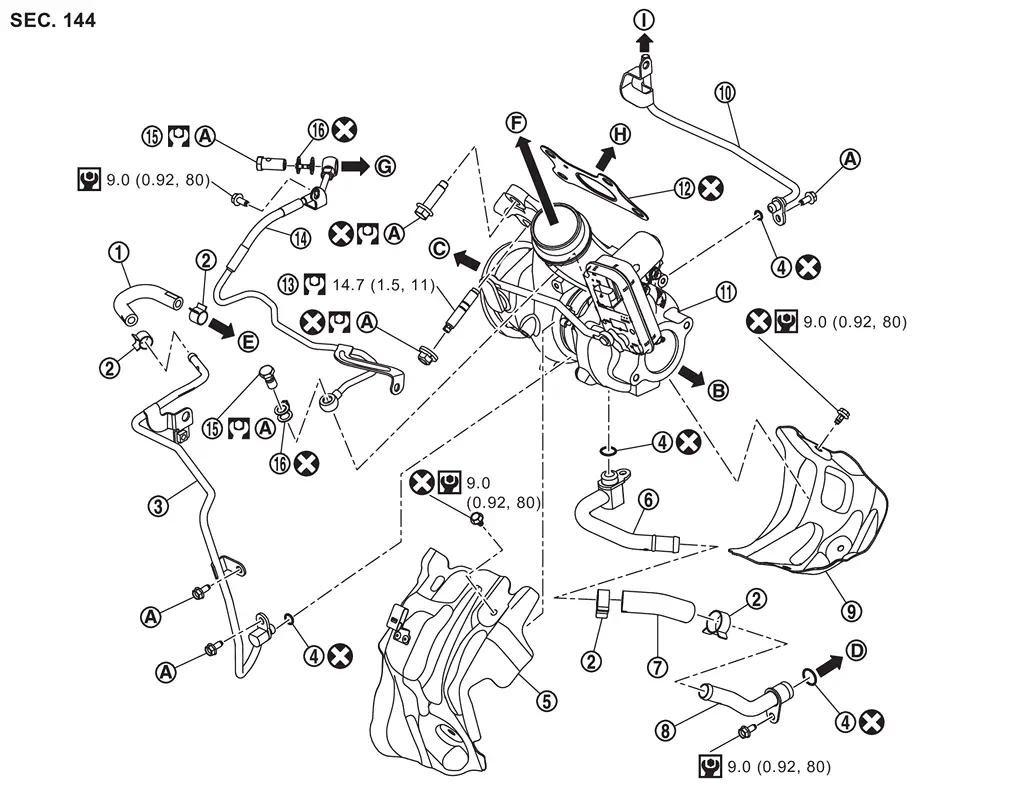
 |
Water inlet hose |  |
Clamp |  |
Water inlet tube |
 |
O-ring |  |
Heat insulator (upper) |  |
Oil return pipe 1 |
 |
Oil return hose |  |
Oil return pipe 2 |  |
Heat insulator (lower) |
 |
Water outlet tube |  |
Turbocharger assembly |  |
Gasket 1 |
 |
Stud bolt |  |
Oil feed tube |  |
Eye bolt |
 |
Gasket 2 | ||||
 |
Comply with the installation procedure when tightening. Refer to Removal & Installation. |  |
To air duct. Refer to Exploded View. |  |
To catalyst converter (bank 2). Refer to Exploded View. |
 |
To lower cylinder block.Refer to Exploded View. |  |
To cylinder head (bank 1). Refer to Exploded View. |  |
To air inlet tube 1. Refer to Exploded View. |
 |
To oil inlet adapter. Refer to Bank 2 side. |  |
To cylinder head (bank 1). Refer to Exploded View. |  |
To water pipe assembly. Refer to Exploded View. |
 : N·m (kg-m, ft-lb) : N·m (kg-m, ft-lb) |
|||||
 : N·m (kg-m, in-lb) : N·m (kg-m, in-lb) |
|||||
 : Always replace after every disassembly. : Always replace after every disassembly. |
|||||
Bank 2 side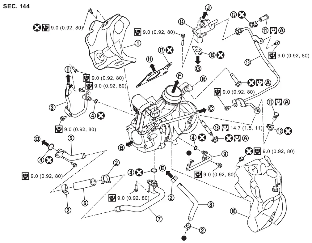
|
Heat insulator (lower) | |
Clamp | |
Water inlet tube |
|
O-ring | |
Oil return pipe 2 | |
Oil return hose |
|
Oil return pipe 1 | |
Water outlet hose | |
Water outlet tube |
|
Heat insulator (upper) | |
Eye bolt | |
Gasket 1 |
|
Oil feed tube | |
Oil inlet adapter | |
Gasket 3 |
|
Turbocharger assembly |  |
Gasket 2 |  |
Stud bolt |
|
Comply with the installation procedure when tightening. Refer to Removal & Installation . | |
To air duct. Refer to Exploded View. | |
To catalyst converter (bank 2). Refer to Exploded View. |
|
To lower cylinder block. Refer to Exploded View. | |
To water pipe 2 assembly. Refer to Exploded View. | |
To air inlet tube 1. Refer to Exploded View. |
|
To cylinder block. Refer to Exploded View. | |
To cylinder head (bank 2). Refer to Exploded View. | |
To electric throttle control actuator. Refer to Exploded View. |
 |
To oil feed tube. Refer to Bank 1 side. | ||||
| : N·m (kg-m, ft-lb) |
|||||
| : N·m (kg-m, in-lb) |
|||||
| : Always replace after every disassembly. |
|||||
 : Indicates that the parts is connected at points with same symbols in actual vehicle. : Indicates that the parts is connected at points with same symbols in actual vehicle. |
|||||
Removal & Installation
WARNING:
-
Jacking up or lift up the vehicle may the vehicle height to go down which cause a personal injury and/or damage to the air suspension component parts. Refer to Precaution for when Jacking and Lifting Up the vehicle with Electronic Air Suspension System.
REMOVAL
Disconnect battery cables from negative terminal. Refer to Exploded View.
Drain engine coolant. Refer to ENGINE COOLANT : Draining.
CAUTION:
-
Perform this step when the engine is cold.
-
Never spill engine coolant on drive belt.
Remove the following parts:
-
Drive belt. Refer to Removal & Installation
-
Air cleaner and air duct assembly. Refer to Removal and Installation.
-
Inlet air duct 2. Refer to Removal and Installation.
-
Air inlet tube 1 and 2. Refer to Removal & Installation.
-
Intake manifold. Refer to Removal and Installation
-
Main muffler. Refer to EXHAUST SYSTEM : Removal & Installation.
Bank 1 side
Remove front tire assembly (RH). Refer to ROAD WHEEL TIRE : Removal & Installation.
Remove fender protector (RH). Refer to Removal and Installation.
Remove 2nd catalyst converter (bank 1). Refer to Removal and Installation.
Remove heat insulator (upper)  .
.
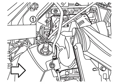
| : Engine front |
Remove catalyst converter (bank 1). Refer to Removal and Installation.
Remove starter motor. Refer to Removal and Installation.
Remove alternator. Refer to Removal and Installation.
Remove oil return pipe 1 from the turbocharger assembly  side.
side.
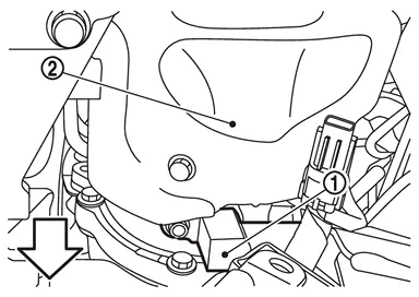
| : Engine front |
Remove air duct 3. Refer to Removal and Installation.
Remove water hose 1. Refer to Removal and Installation
Remove mounting bolt of water outlet tube .
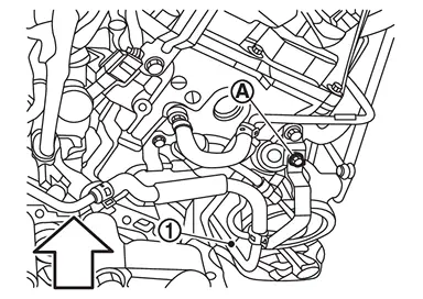
| : Engine upper |
Remove water inlet tube .
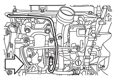
| : Engine front |
Remove mounting bolt of oil feed tube .
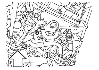
| : Engine upper |
Remove each hose connected to water pipe 1. Refer to Removal and Installation.
Remove water pipe 1. Refer to Removal and Installation.
Remove front heater pipe assembly. Refer to Exploded View.
Remove oil feed tube from the oil inlet adapter side.
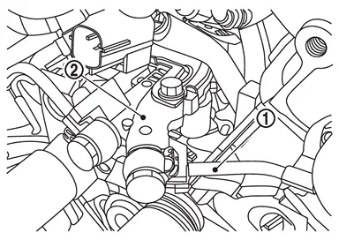
CAUTION:
Do not reuse eye bolt gaskets.
Disconnect turbocharger speed sensor harness connector.
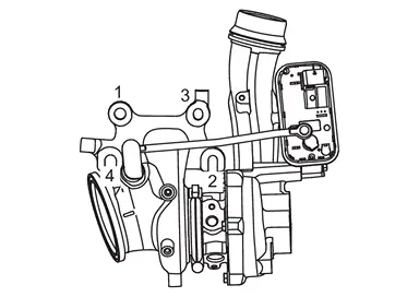
Loosen turbocharger assembly mounting nuts in the order from 4 to 1 as shown in the figure.
Move the turbocharger assembly to the rear of the engine. Remove turbocharger assembly from the top of the engine by rotating it vertically in the following order.
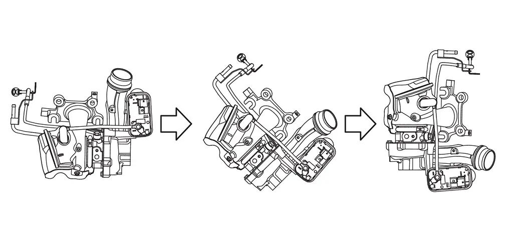
CAUTION:
Be careful not to bend the oil feed tube and water outlet tube.
Remove gasket 1.
CAUTION:
Do not reuse turbocharger gasket.
Bank 2 side
Remove front tire assembly (LH). Refer to ROAD WHEEL TIRE : Removal & Installation.
Remove fender protector (LH). Refer to Removal and Installation.
Release fuel pressure. Refer to Work Procedure.
Discharge refrigerant from A/C circuit. Refer to Recycle Refrigerant.
Remove 2nd catalyst converter. Refer to Removal and Installation.
Remove heat insulator (upper) .
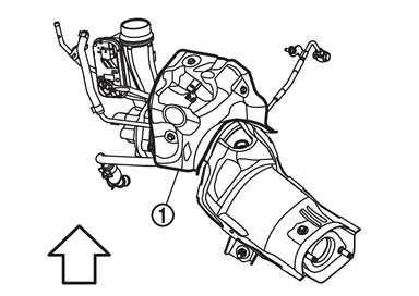
| : Engine upper |
Remove catalyst converter (bank 2). Refer to Removal and Installation.
Remove A/C compressor belt. Refer to Removal & Installation.
Remove EVAP canister purge volume control solenoid valve and the connected hose as a set. Refer to Exploded View.
Remove fuel feed hose. Refer to Removal & Installation.
Remove ground cable. Refer to Exploded View.
Remove each hose connected to water pipe 2. Refer to Removal and Installation.
Remove water pipe 2. Refer to Removal and Installation.
Remove high pressure flexible hose and low pressure flexible hose. Refer to Exploded View.
Remove A/C compressor. Refer to Removal and Installation.
Remove air duct 3. Refer to Removal and Installation.
Remove oil level gauge and oil level gauge guide. Refer to Exploded View.
Disconnect the sub harness connector. Refer to Exploded View.
Remove oil feed tube from the inlet adapter side.
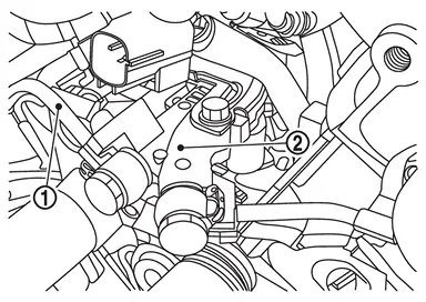
CAUTION:
Do not reuse eye bolt gaskets.
Remove mounting bolt of oil feed tube .
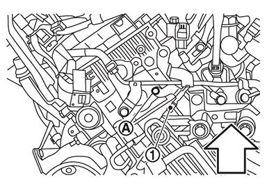
| : Engine upper |
Disconnect turbocharger speed sensor harness connector.
Loosen turbocharger assembly mounting nuts in the order from 4 to 1 as shown in the figure.
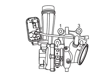
Remove turbocharger assembly.
CAUTION:
Be careful not to bend the oil feed tube and water outlet tube.
Remove gasket 2.
CAUTION:
Do not reuse turbocharger gasket.
Oil feed tube
Fix the turbocharger in a vise (A).
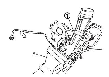
Remove oil feed tube mounting bolts from the turbocharger .
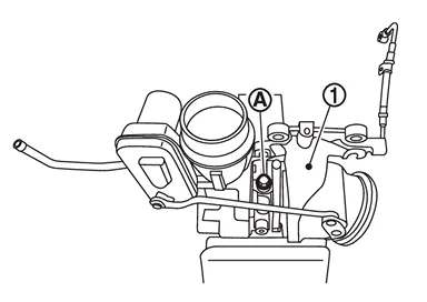
INSTALLATION
 NOTE:
NOTE:
If a turbocharger assembly is replaced, carry out the reset of adaption of “Turbocharger Wastegate Control Solenoid Valve Data Initialization�. Refer to Work Procedure.
Turbocharger side
Install in the reverse order of removal.
Install turbocharger assembly in the reverse order of removal and in the order shown in the figure. (Bank 1 side).
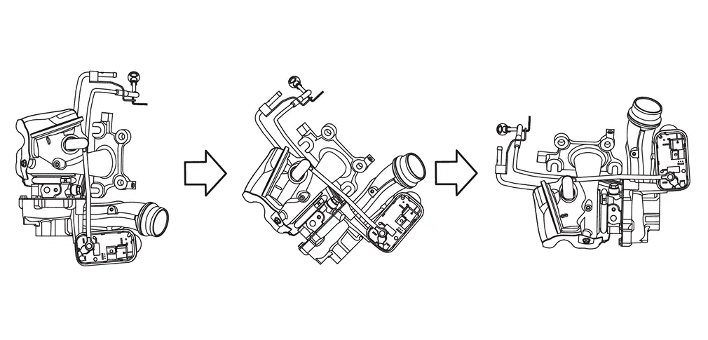
CAUTION:
Be careful not to bend the oil feed tube and water outlet tube.
Install turbocharger assembly in the order from 1 to 4 as shown in the figure.
|
: 34.5 N·m (3.5 kg-m, 25 ft-lb) |
Install oil return pipe.
Install water tube according to the following procedure.
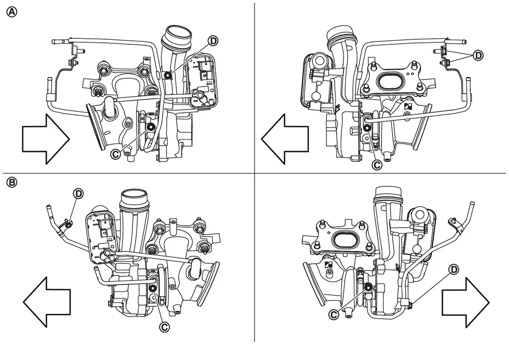
|
: Bank 1 |
|
: Bank 2 |
| : Engine front |
. Temporarily tighten bracket bolt . Tighten water tube bolt to the torque specified below.
|
: 9.0 N·m (0.92 kg-m, 80 in-lb) |
|
: 9.0 N·m (0.92 kg-m, 80 in-lb) |
Install water hose.
-
Align with paint mark (Yellow).
Install the oil feed tube with the following procedure.
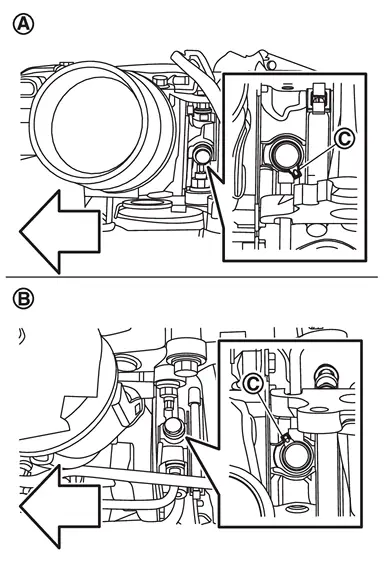
|
: Bank 1 |
|
: Bank 2 |
| : Engine front |
-
Temporarily tighten eye bolt.
-
Tighten eye bolt to the torque specified below.
: 17.0 N·m (1.7 kg-m, 13 ft-lb) CAUTION:
Position gasket protrusion
as shown in the figure.
Oil inlet adapter
Install oil inlet adapter.
Temporarily tighten eye bolt .
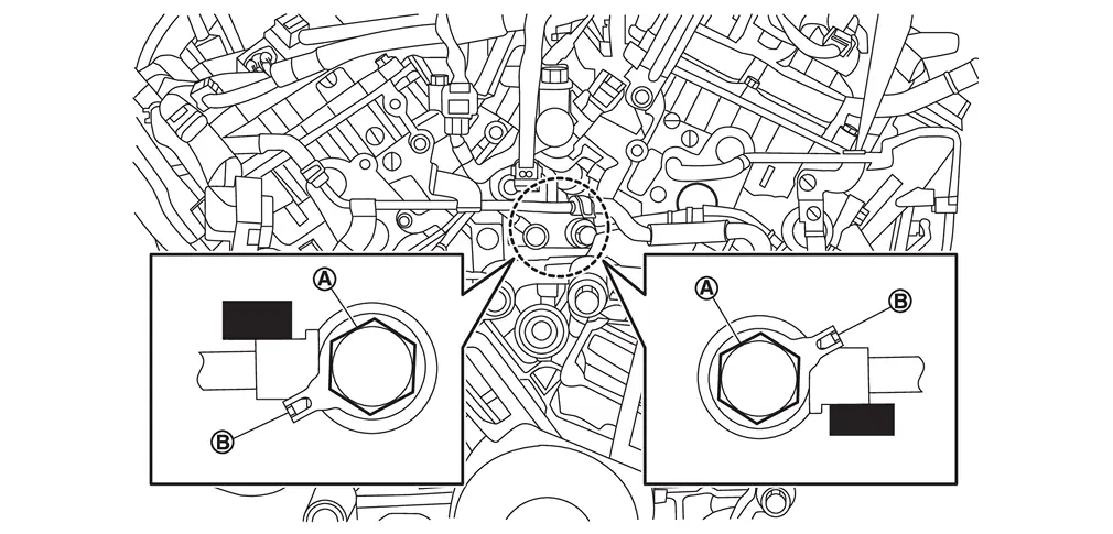
CAUTION:
Position gasket protrusion as shown in the figure.
Temporarily tighten mounting bolt of oil feed tube . (Bank 1 side)
| : vehicle front |
Temporarily tighten mounting bolt of oil feed tube . (Bank 2 side)
| : vehicle front |
Tighten to the specified torque eye bolt .
|
: 25.0 N·m (2.6 kg-m, 18 ft-lb) |
CAUTION:
Position gasket protrusion as shown in the figure.
Tighten to the specified torque mounting bolt of oil feed tube . (Bank 1 side).
| : vehicle front |
|
: 9.0 N·m (0.92 kg-m, 80 in-lb) |
Tighten to the specified torque mounting bolt of oil feed tube . (Bank 2 side).
| : vehicle front |
|
: 9.0 N·m (0.92 kg-m, 80 in-lb) |
Inspection
INSPECTION PROCERDURE
Trouble Diagnosis of Turbocharger
Check items before trouble diagnosis
Check that the engine oil level is between L (Low level) and H (High level) of the oil level gauge. [When the engine oil amount is more then H (High level), the engine oil flows into the inlet duct through the blow-by gas passage, and the turbocharger is misjudged failure.]
Ask the customer if he/she always runs the vehicle in idle engine speed to cool the engine oil down after driving.
-
Replace the turbocharger assembly when any malfunction is found after unit inspections specified in the table below.
-
If no malfunction is found after the unit inspections, judge that the turbocharger body has no non-standard conditions. Check the other parts again.
Inspection Location Result Symptoms likely to occur when the results shown on the left exist. Oil leakage Smoke Noise* Poor power
Poor accelerationTurbine wheel Wet with oil. C A C C Carbon deposits observed. C A B B “Rubs against� housing. C B A B Vane is bent or broken. A A Compressor wheel Inside of intake port is badly stained with oil. B B “Rubs against� housing. C B A B Vane is bent or broken. A A Check both turbine and compressor rotor shaft end play. Heavy feel or catching when turned by hand. C C B Cannot be turned by hand. A Excessively loose bearing. C C B C Rotor shaft, oil return port (Check inside using penlight.) Carbon or sludge deposits in oil drain port. B A C C Boost control valve actuator operation (using a handy pump) -
Does not operate smoothly when air pressure is gradually applied.
-
Stroke amount is not compliance with the air pressure.
A A: Highly possible. B: Possible. C: May exist. * Racing under cold engine may generate a noise from the area of wastegate valve. This is not a turbocharger malfunction. The noise stops after engine warm-up.
-
INSPECTION AFTER REMOVAL
Bank1 side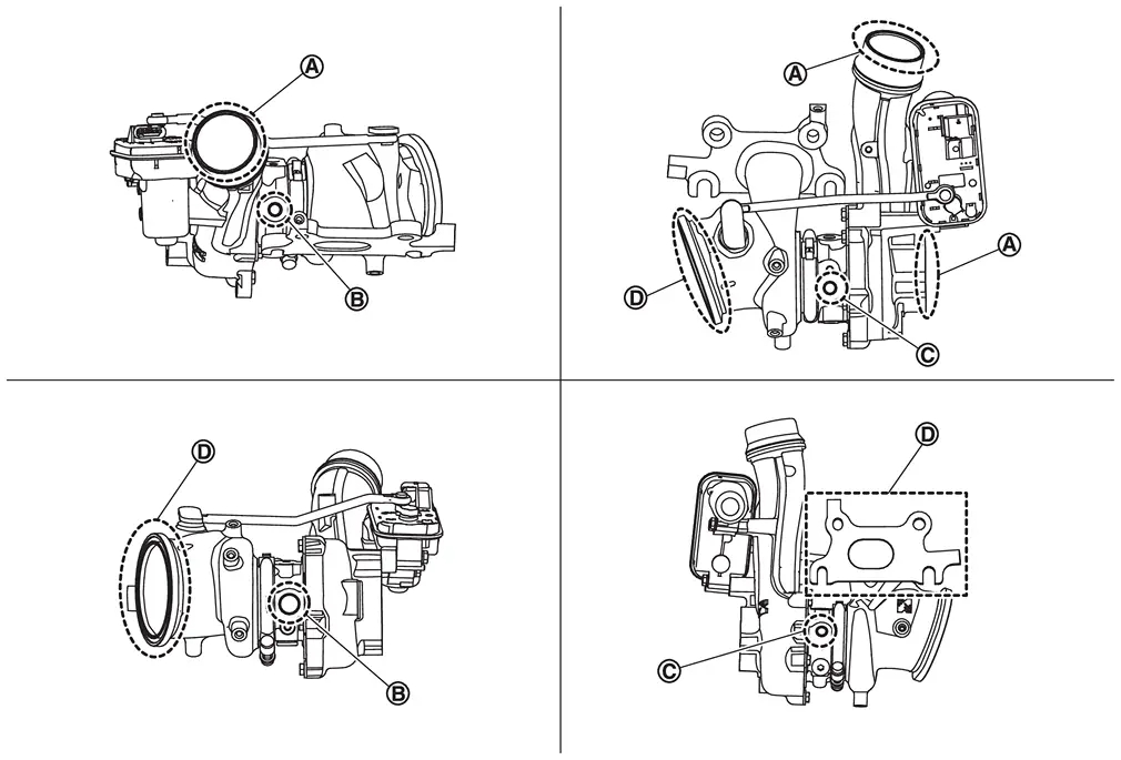
|
Location to check for air leaks | |
Location to check for engine oil leaks | |
Location to check for engine coolant leaks |
|
Location to check for exhaust gas leaks |
Bank2 side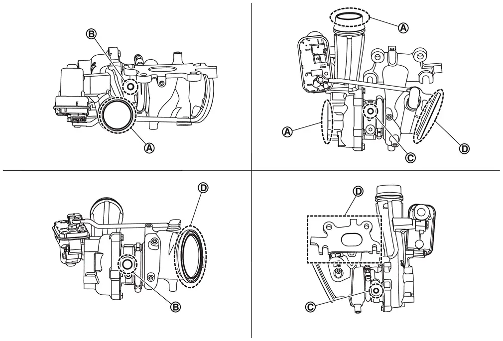
|
Location to check for air leaks | |
Location to check for engine oil leaks | |
Location to check for engine coolant leaks |
|
Location to check for exhaust gas leaks |
CAUTION:
When the compressor wheel, turbine wheel or rotor shaft is damaged, remove all the fragments and foreign matter left in the following passages in order to prevent a secondary failure:
| Intake side | : Between turbocharger and charge air cooler |
| Exhaust side | : Between turbocharger and outlet duct |
INSPECTION AFTER INSTALLATION
Start engine and raise engine speed to check no exhaust emission leaks.
Other materials
Excessive Operation Frequency
Description
VDC function, TCS function, ABS function, EBD function, brake limited slip differential (BLSD) function, brake assist function, hill start assist function, advanced hill descent control function (4WD models) and trailer sway control function operates in excessive operation frequency.
Dia ...
Dash Side Finisher
Removal and Installation
CAUTION:
Never damage the body panel.REMOVALRemove front kicking plate. Refer to Removal and Installation.
Remove hood lock control handle (driver side). Refer to Removal and Installation.
Disengage dash trim clip from dash side finisher.
Disengage dash side finisher fixi ...
Around View Monitor
Symptom Table
AROUND VIEW MONITOR SYSTEM Symptoms Check items Probable malfunction location
Screen is not switched to camera image, when camera switch is pressed and when shift position is shifted to the reverse position.
“AROUND VIEW MONITOR� is not displayed on the system selection scree ...