Exploded View
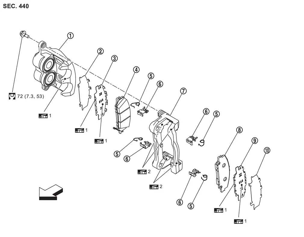
 |
Cylinder body |  |
Inner shim cover |  |
Inner shim |
 |
Inner pad (with pad wear sensor) |  |
Return spring |  |
Pad retainer |
 |
Torque member |  |
Outer pad |  |
Outer shim |
 |
Outer shim cover | ||||
| : vehicle front | |||||
 1: Apply MOLYKOTE® AS880N or siliconebased grease. 1: Apply MOLYKOTE® AS880N or siliconebased grease. |
|||||
| 2: Apply MOLYKOTE® 7439 or equivalent. |
|||||
 : N·m (kg-m, ft-lb) : N·m (kg-m, ft-lb) |
|||||
Molykote is a registered trademark of Dow Corning Corporation.
Removal and Installation
WARNING:
-
Jacking up or lift up the vehicle may the vehicle height to go down which cause a personal injury and/or damage to the air suspension component parts. Refer to Precaution for when Jacking and Lifting Up the vehicle with Electronic Air Suspension System.
REMOVAL
WARNING:
Since dust covering the front and rear brakes has an affect on human body, the dust must be removed with a dust collector. Never splatter the dust with an air blow gun.
CAUTION:
-
Never depress the brake pedal while removing the brake pads because the piston may pop out.
-
If the brake fluid or grease adheres to the brake caliper assembly and disc rotor, quickly wipe it off.
Remove tires. Refer to ROAD WHEEL TIRE : Removal & Installation.
Remove lower sliding pin bolt  , and remove cylinder body.
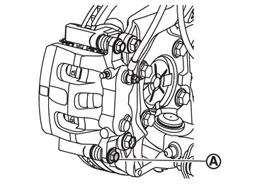
Suspend the cylinder body with suitable wire so that the brake hose will not stretch.
Remove the brake pads, shims, shim covers and pad retainer (with return spring ) from the torque member .
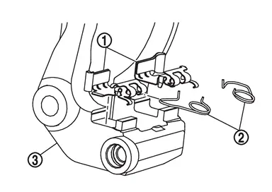
CAUTION:
-
Remove pad retainer together with pad return springs.
-
Never deform the pad return springs and pad retainer when removing the pad retainer from the torque member.
-
Never damage the piston boots.
-
Never drop the brake pads, shims and shim covers.
-
Remember each position of the removed brake pads.
Remove the return springs from the pad retainer .
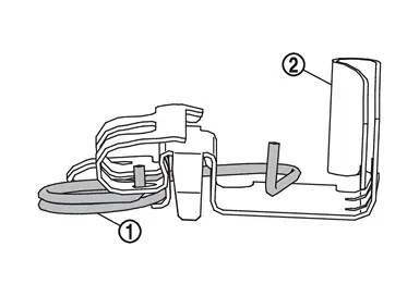
CAUTION:
Never deform the return springs when removing the return springs from the pad retainer.
Perform inspection after removal. Refer to Inspection.
INSTALLATION
WARNING:
Since dust covering the front and rear brakes has an affect on human body, the dust must be removed with a dust collector. Never splatter the dust with an air blow gun.
CAUTION:
-
Never depress the brake pedal while removing the brake pads because the piston may pop out.
-
If the brake fluid or grease adheres to the brake caliper assembly and disc rotor, quickly wipe it off.
Install the return springs to pad retainer if the return springs has been removed.
CAUTION:
Never deform the return springs.
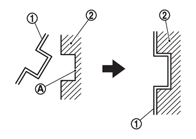
Apply MOLYKOTE® 7439 or equivalent to the match face between the pad retainers and torque member if the pad retainers has been removed.
Molykote is a registered trademark of Dow Corning Corporation.
Install the pad retainer (with return spring ) to torque member if the pad retainers has been removed.
CAUTION:
-
Securely assemble the pad retainers so that it will not be lifted up from the torque member.
-
Never deform the pad retainers and return springs.
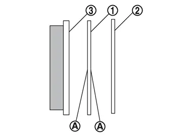
Apply MOLYKOTE® AS880N or siliconebased grease to the both face of shim , and install the shim and the shim covers to the brake pad .
CAUTION:
-
Always replace the shims and shim covers when replacing the brake pad.
-
Never grease must not protrude beyond shim.
Molykote is a registered trademark of Dow Corning Corporation.
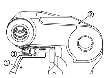
Install the brake pads to the torque member .
CAUTION:
Both inner and outer pads have a pad return system. Securely push the return spring into the disc rotor side with brake pad.
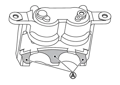
Apply MOLYKOTE® AS880N or siliconebased grease to the claw parts of cylinder body.
Molykote is a registered trademark of Dow Corning Corporation.
Install cylinder body to torque member.
CAUTION:
-
Never damage the piston boot.
-
When replacing brake pad with new one, check a brake fluid level in the reservoir tank because brake fluid returns to reservoir tank when pressing piston in.
 NOTE:
NOTE:
Use a brake caliper wrench (commercial service tool) to easily press piston.
Install the lower sliding pin bolt and tighten it to the specified torque. Refer to Exploded View.
Depress the brake pedal several times to check that no drag feel is present for the front disc brake. Refer to Inspection and Adjustment.
Install tires. Refer to ROAD WHEEL TIRE : Removal & Installation.
Inspection
INSPECTION AFTER REMOVAL
-
Replace the shims and shim covers if rust is excessively attached.
-
Eliminate rust on the return spring, pad retainers and the torque member. Replace them if rust is excessively attached.
INSPECTION AFTER INSTALLATION
-
Check a drag of front disc brake. If any drag is found, follow the procedure described below.
Remove brake pads. Refer to Removal and Installation.
Press the pistons.
Install brake pads. Refer to Removal and Installation.
Depress the brake pedal several times.
Check a drag of front disc brake again. If any drag is found, disassemble the cylinder body. Refer to FRONT BRAKE CALIPER ASSEMBLY : Disassembly & Assembly.
Burnish contact surfaces brake pads and disc rotor after refinishing or replacing brake pads, or if a soft pedal occurs at very low mileage. Refer to Inspection and Adjustment.
Other materials
Precautions
Precaution for Supplemental Restraint System (SRS) "AIR BAG" and "SEAT BELT PRE-TENSIONER"
The Supplemental Restraint System such as “AIR BAG” and “SEAT BELT PRE-TENSIONER”, used along with a front seat belt, helps to reduce the risk or severity of injury to the driver and front passenger fo ...
Lumbar Support Unit
Removal and Installation
REMOVALRemove front seatback blower motor. Refer to Removal and Installation.
Disengage fixing portions and then remove front seat lumbar support unit.
Disconnect front seat pneumatic control unit connector (4 way lumbar support) or front seat lumbar support air pump conn ...
Tilt & Telescopic
Diagnosis Procedure
CHECK STEERING COLUMN CONTROL MODULE POWER SUPPLY AND GROUND CIRCUIT
Check steering column control module power supply and ground circuit. Refer to Diagnosis Procedure.
Is the inspection result normal?
YES>>
GO TO 2.
NO>>
Repair or replace the malfunctioning parts.
...