Precaution for Supplemental Restraint System (SRS) "AIR BAG" and "SEAT BELT PRE-TENSIONER"
The Supplemental Restraint System such as “AIR BAG� and “SEAT BELT PRE-TENSIONER�, used along with a front seat belt, helps to reduce the risk or severity of injury to the driver and front passenger for certain types of collision.
Information necessary to service the system safely is included in the “SRS AIR BAG� and “SEAT BELT� of this Service Manual.
WARNING:
Always observe the following items for preventing accidental activation.
-
To avoid rendering the SRS inoperative, which could increase the risk of personal injury or death in the event of a collision that would result in air bag inflation, it is recommended that all maintenance and repair be performed by an authorized NISSAN/INFINITI dealer.
-
Improper repair, including incorrect removal and installation of the SRS, can lead to personal injury caused by unintentional activation of the system. For removal of Spiral Cable and Air Bag Module, see “SRS AIR BAG�.
-
Never use electrical test equipment on any circuit related to the SRS unless instructed to in this Service Manual. SRS wiring harnesses can be identified by yellow and/or orange harnesses or harness connectors.
PRECAUTIONS WHEN USING POWER TOOLS (AIR OR ELECTRIC) AND HAMMERS
WARNING:
Always observe the following items for preventing accidental activation.
-
When using air or electric power tools or hammers, always switch the ignition/power switch OFF, disconnect the 12V battery or batteries, and wait at least 3 minutes before performing any service.
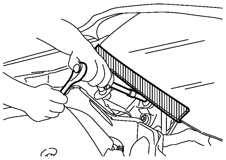
Precaution for Procedure without Cowl Top Cover
When performing the procedure after removing cowl top cover, cover the lower end of windshield with urethane, etc to prevent damage to windshield.
Precautions for Removing Battery Terminal
-
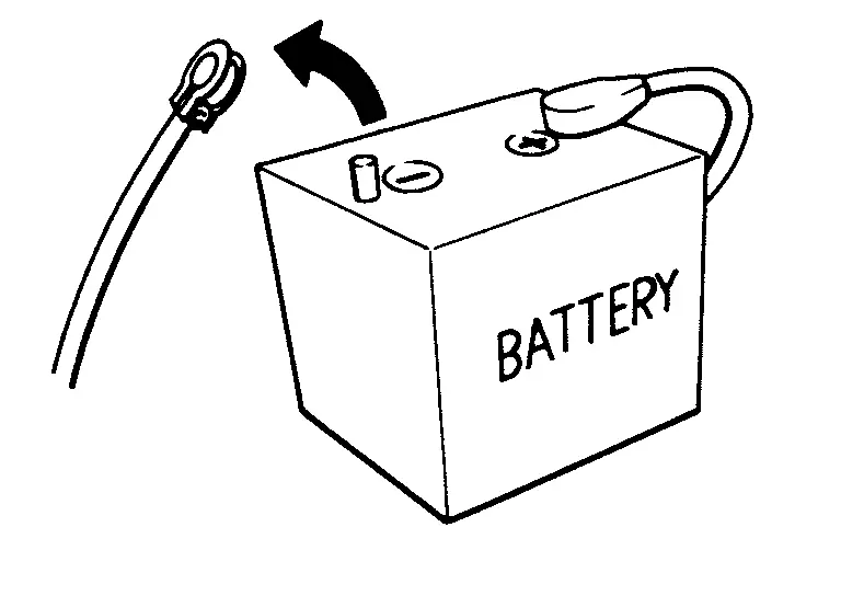
When disconnecting the 12V battery terminal, turn off the ACC power before disconnecting the 12V battery terminal, observing “How to disconnect 12V battery terminal� described below.
 NOTE:
NOTE:
Some ECUs operate for a certain fixed time even after ignition switch is turned OFF and ignition power supply is stopped. If the battery terminal is disconnected before ECU stops, accidental DTC detection or ECU data damage may occur.
-
For Nissan Armada vehicles with the 2-batteries, be sure to connect the main battery and the sub battery before turning ON the ignition switch.
NOTE:
If the ignition switch is turned ON with any one of the terminals of main battery and sub battery disconnected, then DTC may be detected.
-
After installing the 12V battery, always check "Self Diagnosis Result" of all ECUs and erase DTC.
NOTE:
The removal of 12V battery may cause a DTC detection error.
HOW TO DISCONNECT 12V BATTERY TERMINAL
Disconnect 12V battery terminal according to instruction described below.
-
Open the hood.
-
Turn ignition switch to the ON position.
-
Turn ignition switch to the OFF position with the driver side door opened.
-
Get out of the vehicle and close the driver side door.
-
Wait at least 3 minutes. For vehicle with the engine listed below, remove the battery terminal after a lapse of the specified time.
BR08DE : 4 minutes R9N engine : 12 minutes BR10DE : 12 minutes V9X engine : 4 minutes D4D engine : 20 minutes YD25DDTi : 2 minutes HR09DET : 12 minutes YS23DDT : 4 minutes HR10DDT : 12 minutes YS23DDTT : 4 minutes HR10DET : 12 minutes ZD30DDTi : 60 seconds HR13DDT : 12 minutes ZD30DDTT : 60 seconds HRA2DDT : 12 minutes K9K engine : 4 minutes M9R engine : 4 minutes R9M engine : 4 minutes CAUTION:
While waiting, never operate the vehicle such as locking, opening, and closing doors. Violation of this caution results in the activation of ACC power supply according to the Auto ACC function.
-
Remove 12V battery terminal.
CAUTION:
After installing 12V battery, always check self-diagnosis results of all ECUs and erase DTC.
On Board Diagnostic (OBD) System of Engine and A/T
The ECM and TCM have an on board diagnostic system. It will illuminate the malfunction indicator lamp (MIL) to warn the driver of a malfunction causing emission deterioration.
CAUTION:
-
Always turn the ignition switch OFF and disconnect the negative battery cable before any repair or inspection work. The open/short circuit of related switches, sensors, solenoid valves, etc. will cause the MIL to illuminate.
-
Always connect and lock the connectors securely after work. A loose (unlocked) connector will cause the MIL to illuminate due to the open circuit. (Be sure the connector is free from water, grease, dirt, bent terminals, etc.)
-
Certain systems and components, especially those related to OBD, may use a new style slide-locking type harness connector. For description and how to disconnect, refer to Harness Connector.
-
Always route and secure the harnesses properly after work. The interference of the harness with a bracket, etc. may cause the MIL to illuminate due to the short circuit.
-
Always connect rubber tubes properly after work. A misconnected or disconnected rubber tube may cause the MIL to illuminate due to the malfunction of the EVAP system or fuel injection system, etc.
-
Always erase the unnecessary malfunction information (repairs completed) from the ECM and TCM (Transmission control module) before returning the vehicle to the customer.
General Precautions
-
Ignition switch OFF and disconnect the battery cable from the negative terminal before connecting or disconnecting the A/T assembly connector. Because battery voltage is applied to TCM even if ignition switch is switched OFF.
-
Perform “DTC (Diagnostic Trouble Code) CONFIRMATION PROCEDURE� after performing each TROUBLE DIAGNOSIS.
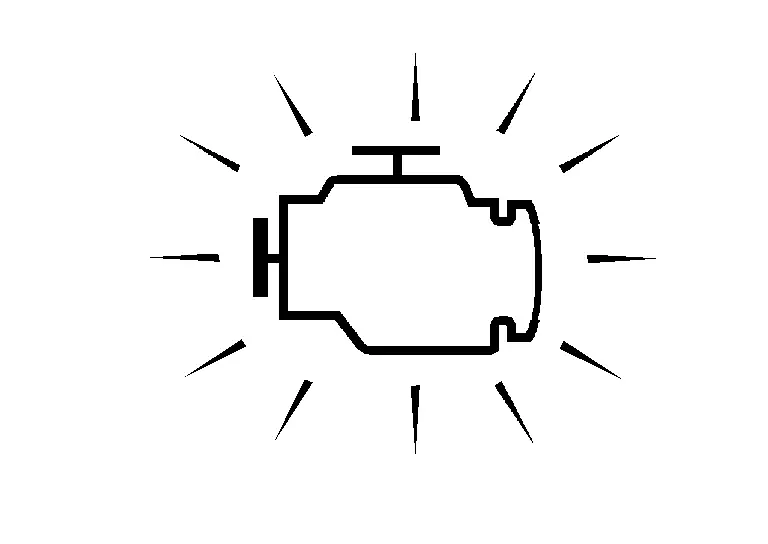
If the repair is completed DTC should not be displayed in the “DTC CONFIRMATION PROCEDURE�.
-
Always use the specified brand of ATF.
-
Use lint-free paper not cloth rags during work.
-
Dispose of the waste oil using the methods prescribed by law, ordinance, etc. after replacing the ATF.
-
Before proceeding with disassembly, thoroughly clean the outside of the transmission. It is important to prevent the internal parts from becoming contaminated by dirt or other foreign matter.
-
Disassembly should be done in a clean work area.
-
Use lint-free paper or towels for wiping parts clean. Common shop rags can leave fibers that could interfere with the operation of the transmission.
-
Place disassembled parts in order for easier and proper assembly.
-
All parts should be carefully cleaned with a general purpose, non-flammable solvent before inspection or reassembly.
-
Gaskets, seals and O-rings should be replaced any time the A/T is disassembled.
-
It is very important to perform functional tests whenever they are indicated.
-
Properly installed valves, sleeves, plugs, etc. will slide along bores in valve body under their own weight.
-
Before assembly, apply a coat of recommended ATF to all parts. Apply petroleum jelly to protect O-rings and seals, or hold bearings and washers in place during assembly. Never use grease.
-
Extreme care should be taken to avoid damage to O-rings, seals and gaskets when assembling.
-
Occasionally, the parking gear may be locked with the torque insufficiently released, when stopping the vehicle by switching the shift position from “D� or “R� to “P� position with the brake pedal depressed.
In this case, the shock with a thud caused by the abrupt release of torque may occur when switching the shift position “P� position to other positions.
However, this symptom is not a malfunction which results in the damage of parts.
-
To avoid the risk of minor injury or property damage: If the 12-volt battery has low or no voltage, the transmission cannot be shifted. Replace the battery or repair the damaged power supply system. If towing the vehicle, follow the tow procedure, refer to Tow Truck Towing.
Service Notice or Precaution
ATF COOLER SERVICE
If ATF contains frictional material (clutches, bands, etc.), or if an A/T is repaired, overhauled, or replaced, inspect and clean the A/T fluid cooler mounted in the radiator or replace the radiator. Flush cooler lines using cleaning solvent and compressed air after repair. For A/T fluid cooler cleaning procedure, refer to Cleaning. For radiator replacement, refer to RADIATOR : Exploded View.
Precaution for when Jacking and Lifting Up the Vehicle with Electronic Air Suspension System
WARNING:
-
When jacking up or lift up the vehicle, always turn OFF the electronic air suspension function with the vehicle unladen and normal height, since the suspension may accidentally move and it can lead to personal injury.
-
When removing the air suspension component parts, always follow the removing procedure since the vehicle height may accidentally drop and it can lead to personal injury.
CAUTION:
When jacking up or lift up the vehicle, always turn OFF the electronic air suspension function with the vehicle unladen and normal height to prevent damage to the air suspension component parts.
OPERATION PROCEDURE
Jacking up or lift up using the following steps.
-
Start engine.
-
Turn auto height mode control switch to ON, shift the shift position to N and set to normal height.
-
Turn OFF the electronic air suspension function. Refer to Operation.
-
Stop engine.
-
Jacking up or lift up.
Precaution for Electronic Air Suspension System
WARNING:
-
When removing the air suspension component parts, always follow the removing procedure since the vehicle height may accidentally drop and it can lead to personal injury.
CAUTION:
-
Never expand and contract the air spring of shock absorber.
-
Never expand and contract the air spring.
-
Never let foreign materials entered into parts.
-
Always check for the air leakage with soapy water after working.
-
Be sure to close the hood after working.
-
Turn ON the electronic air suspension function after working. Refer to Operation.
-
Air suspension component parts may be rusted if de-icer is put in excessively to prevent freezing because it cannot remove moisture in pneumatic circuit.
-
Replacing suspension component parts other than genuine parts may cause low performance of air suspension and calibration failure.
Other materials
Front
Exploded View
Side defroster nozzle RH
Center defroster nozzle
Side defroster nozzle LH
Instrument panel assembly
Side ventilator grille LH
Instrument finisher A
Ionizer
(with ionizer models)
Side ventilator duct 1 LH
Side ventilator duct 3 LH
Side ventilator duct 2 L ...
Front Heated Seat System
Symptom Table
Symptom Possible causeInspection item
Front heated seat system does not operate
Only the display unit operation does not operate
Check AV system
Display unit and multifunction switch operation does not operate
Fuse
Front seat heater power supply/ground/LIN signal circuit
Front seat ...
Warning Chime System
Precautions
Precaution for Supplemental Restraint System (SRS) "AIR BAG" and "SEAT BELT PRE-TENSIONER"
The Supplemental Restraint System such as “AIR BAG� and “SEAT BELT PRE-TENSIONER�, used along with a front seat belt, helps to reduce the risk or severity of injury to the driver and front ...