
Nissan Armada 2025-2026 Service and Repair Manual: Connector Information
HOW TO USE CONNECTOR INFORMATION
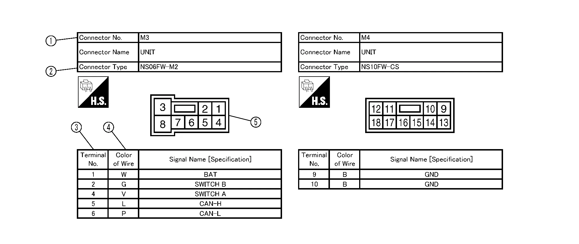
| Number | Item | Description | |
|---|---|---|---|
 | Connector number |
| |
 | Connector type |
 : Special type : Special type |
|
 | Terminal number |
| |
 | Wire color |
| |
B = Black W = White R = Red G = Green L = Blue Y = Yellow LG = Light Green BG or BE = Beige LA = Lavender | BR = Brown OR or O = Orange P = Pink PU or V (Violet) = Purple GY or GR = Gray SB = Sky Blue CH = Dark Brown DG = Dark Green | ||
| |||
| Connector |
| |
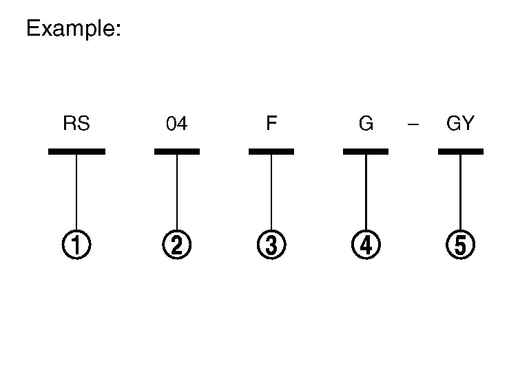

 Sample/Wiring Diagram -Example-
Each section includes wiring diagrams.
Description Number Item Description Power supply This means the power supply of fusible link or fuse.
Fuse “/� means the fuse.
Current rating of fusi ...
Other materials:
Work Procedure
Perform camera calibration and perform writing to the around view monitor control unit, after removal/installation or replacement of each camera or camera mounting parts (front bumper molding center, door mirror, or others), or replacement of around view monitor control unit.
Parts name Operatio ...
Precaution for Automatic Brake Hold
Do not disassemble chassis control module.
Do not use any parts that have been dropped.
Do not perform active test during driving.
Do not operate automatic brake hold function on a steep slope or a slippery road. (The vehicle may move even when automatic brake hold function is applied.)
When the sto ...
Exploded View
A/T assembly A/T fluid warmer O-ring : N·m (kg-m, in-lb) : Always replace after every disassembly. : Apply ATF ...

0.0068