Description
-
When CONSULT/GST is connected with a data link connector (A) equipped on the vehicle side, it will communicate with the control unit equipped in the vehicle and then enable various kinds of diagnostic tests.
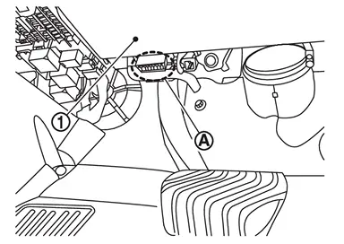
1 : Instrument lower panel LH -
Refer to “CONSULT Software Operation Manual� for more information.
CONSULT Function and System Application1
FUNCTION
| Mode | Function |
|---|---|
| All DTC Reading | Display all DTCs or diagnostic items that all ECUs are recording and judging. |
| Work Support | This mode enables a technician to adjust some devices faster and more accurately. |
| Self Diagnostic Results | Retrieve DTC from ECU and display diagnostic items. |
| Data Monitor | Monitor the input/output signal of the control unit in real time. |
| Network diagnosis | This mode displays a network diagnosis result about CAN. |
| Active Test | Send the drive signal from CONSULT to the actuator. The operation check can be performed. |
| ECU Identification | Display the ECU identification number (part number etc.) of the selected system. |
| Replace ECU | Automatically execute the programming and config required when replacing the ECU. |
| SRT&P-DTC Confirmation | The state of System Readiness Test (SRT) items, the presence or absence of permanent DTC*, and driving conditions can be checked. |
| DTC work support | DTC reproduction procedure can be performed speedily and precisely. |
| Others | Other results or histories, etc. that are recorded in ECU are displayed. |
*: Permanent DTC is not applied for regions where it is not mandated.
SYSTEM APPLICATION*1
| System | All DTC Reading | Work Support | Self Diagnostic Results | Data Monitor | Network diagnosis | Active Test | ECU Identification | Replace ECU | SRT&P-DTC Confirmation | DTC work support | Others |
|---|---|---|---|---|---|---|---|---|---|---|---|
| ECM | x | x | x | x | x | x | x | x | x*2 | x | - |
| TRANSMISSION | x | x | x | x | x | - | x | x | x*2 | - | - |
| AIR BAG | x | - | x | x | x | - | x | x | - | - |
|
| COMBINATION METER | x | - | x | x | x | - | x | x | - | - |
|
| AUTOMATIC BACK DOOR | x | - | x | x | x | - | x | - | - | - | - |
| BCM | x | x | x | x | x | x | x | x | - | - | - |
| DRIVER SEAT | x | - | x | x | x | x | x | - | - | - | - |
| ABS | x | x | x | x | x | x | x | x | - | - | - |
| IPDM E/R | x | x | x | x | x | x | x | x | - | - | - |
| MULTI AV | x | x | x | x | x | - | x | x | - | - | - |
| AROUND VIEW MONITOR | x | x | x | x | x | - | x | x | - | - | - |
| SONAR | x | x | x | x | x | - | x | x | - | - | - |
| ICC/ADAS 2 | x | x | x | x | x | x | x | x | - | - | - |
| AIR PRESSURE MONITOR | x | x | x | x | - | - | - | - | - | - | - |
| PRECRASH SEAT BELT | x | x | x | x | x | - | x | - | - | - | - |
| HVAC | - | x | x | x | x | x | x | - | - | - | - |
| LASER/RADAR | x | x | x | x | x | - | x | x | - | - | - |
| HIGH BEAM ASSIST | x | - | x | x | x | x | x | x | - | - | - |
| LANE CAMERA | x | x | x | x | x | - | x | x | - | - | - |
| E-SUS | x | x | x | x | x | x | x | - | - | - | - |
| Side radar (Rear left) | x | x | x | x | x | x | x | x | - | - | - |
| Side radar (Rear right) | x | x | x | x | x | x | x | x | - | - | - |
| 8ch CAN GATEWAY 2 | x | x | x | - | x | - | x | x | - | - | - |
| 8ch CAN GATEWAY 3 | x | x | x | - | - | - | x | x | - | - | - |
| WIRELESS CHARGER UNIT | x | x | x | x | x | x | x | x | - | - | - |
| IVC | x | x | x | x | x | - | x | x | - | - | - |
| OCCUPANT DETECTION | - | x | - | x | - | - | - | - | - | - | - |
| INTELLIGENT KEY | x | x | x | x | x | - | x | x | - | - | - |
| Air suspension | x | x | x | x | x | - | x | x | - | - | - |
| BRAKE | x | - | x | x | x | x | x | x | - | - | - |
| AUDIO AMPLIFIER | x | x | x | x | x | - | x | x | - | - | - |
| DRIVING VIDEO RECORDER | x | x | x | - | x | - | x | x | - | - | - |
| LITHIUM ION BATTERY 12V | x | - | x | x | x | - | x | x | - | - | - |
| AWD/4WD | x | x | x | x | x | - | x | x | - | - | - |
| driver monitor camera | x | x | x | x | x | - | x | x | - | - | - |
| Side radar (Front left) | x | x | x | x | x | - | x | x | - | - | - |
| Side radar (Front right) | x | x | x | x | x | - | x | x | - | - | - |
| HD MAP | x | x | x | x | x | - | x | - | - | - | - |
| PNS relay | x | - | x | x | x | - | x | - | - | - | - |
| STEERING COLUMN | x | - | x | x | x | x | x | - | - | - | - |
| PASSENGER SEAT | x | - | x | x | x | x | x | - | - | - | - |
| DISPLAY UNIT | x | - | x | x | x | - | x | x | - | - | - |
| HEAD UP DISPLAY | x | x | x | x | x | - | x | x | - | - | - |
| CHASSIS CONTROL | x | x | x | x | x | x | x | x | - | - | - |
| EPS/DIRECT ADAPTIVE STEERING 3 | x | x | x | x | x | - | x | x | - | - | - |
| THIRD SEAT RH | x | x | x | x | x | x | x | - | - | - | - |
| Sub-TCM | x | x | x | x | x | - | x | x | - | - | - |
| ELECTRIC SHIFTER | x | - | x | - | x | - | x | x | - | - | - |
| Front control panel | x | - | x | - | - | - | x | x | - | - | - |
| DIFFERENTIAL LOCK | x | - | x | x | x | - | x | x | - | - | - |
x: Applicable
*1: If GST application is equipped, functions in accordance with SAE J1979 and ISO 15031-5 can be used.
*2: Permanent DTC is not applied for regions where it is not mandated.
CONSULT/GST Data Link Connector (DLC) Circuit
INSPECTION PROCEDURE
If the CONSULT/GST cannot diagnose the system properly, check the following items.
| Symptom | Check item |
|---|---|
| CONSULT/GST cannot access any system. |
|
| CONSULT cannot access individual system. (Other systems can be accessed.) |
|
 NOTE:
NOTE:
The DDL1 and DDL2 circuits from DLC pins 12, 13, 14 and 15 may be connected to more than one system. A short in a DDL circuit connected to a control unit in one system may affect CONSULT access to other systems.
If the GST cannot operate properly, check the circuit based on the information of SAE J1962 and ISO 15031-3.
Wiring Diagram - CONSULT/GST CHECKING SYSTEM -
CONSULT CHECKING SYSTEM (WITHOUT ProPILOT Assist 2.1)
Click Link to Wiring Diagram.
CONSULT CHECKING SYSTEM (WITH ProPILOT Assist 2.1)
Click Link to Wiring Diagram.
Other materials
Unbalance Steering Wheel Turning Force (torque Variation)
Description
Unbalance steering wheel turning force (torque variation).
Diagnosis Procedure
PERFORM SELF-DIAGNOSIS
With CONSULT
Pull the parking brake switch.
NOTE:
Check to make sure that the parking brake switch indicator is turned ON.
Ignition switch OFF.
Get out of the vehicle and close all ...
Front Seat
Exploded View
REMOVAL
Headrest
Front seat assembly
(passenger seat)
Front seat assembly
(driver seat)
Seat leg cover
: Pawl
: N·m (kg-m, ft-lb)
DISASSEMBLYDriver Seat WITH 8WAY POWER SEAT SYSTEM
Headrest holder (lock)
Headrest holder (free)
Sea ...
Passenger Door Mirror Control Module
Exploded View
Passenger door mirror control module
Clip
Front door panel
: vehicle front
Removal and Installation
REMOVALRemove front door finisher (passenger side). Refer to Removal & Installation.
Disconnect harness connector.
Disengage passenger door mirror control module fixin ...