Work Flow (With EXP-800 NI or GR8-1200 NI)
CHARGING SYSTEM DIAGNOSIS WITH EXP-800 NI OR GR8-1200 NI
To test the charging system, use the following special service tools:
-
EXP-800 NI Battery and electrical diagnostic analyzer
-
GR8-1200 NI Multitasking battery and electrical diagnostic station
 NOTE:
NOTE:
Refer to the applicable Instruction Manual for proper charging system diagnosis procedures.
OVERALL SEQUENCE
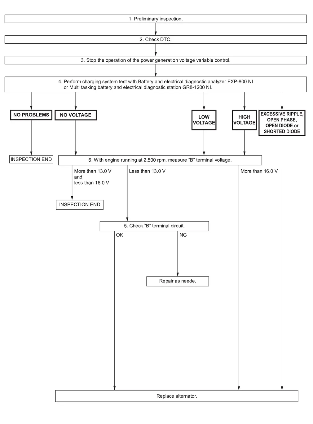
DETAILED FLOW
NOTE:
To ensure a complete and thorough diagnosis, the 12V battery, starter motor and alternator test segments must be done as a set from start to finish.
PRELIMINARY INSPECTION
Perform preliminary inspection. Refer to Refer to Inspection Procedure.
>>
GO TO 2.
CHECK FOR DTC
Perform self diagnosis with CONSULT.
Is applicable DTC detected?
YES-1>>B12A4-81: Refer to DTC Description.
YES-2>>B12A4-92: Refer to DTC Description.
YES-3>>Other than above: Refer to DTC Index.
NO>>GO TO 3.
STOP POWER GENERATION VOLTAGE VARIABLE CONTROL SYSTEM
Ignition switch OFF, and disconnect battery current sensor connector to stop operation of power generation voltage variable control system. (However, DTC might remain. After finishing the inspection, connect battery current sensor connector, and then erase self-diagnostic results history using CONSULT.)
>>
GO TO 4.
DIAGNOSIS WITH EXP-800 NI OR GR8-1200 NI
Perform the charging system test using Multi tasking battery and electrical diagnostic station GR8-1200 NI or Battery and electrical diagnostic analyzer EXP-800 NI. Refer to the applicable Instruction Manual for proper testing procedures.
Test result
NO PROBLEMS>>INSPECTION END
NO VOLTAGE>>GO TO 5.
LOW VOLTAGE>>GO TO 6.
HIGH VOLTAGE>>GO TO 6.
EXCESSIVE RIPPLE, OPEN PHASE, OPEN DIODE or SHORTED DIODE>>Replace alternator. Refer to Removal and Installation.
“B� TERMINAL CIRCUIT INSPECTION
Check “B� terminal circuit. Refer to Diagnosis Procedure.
Is “B� terminal circuit normal?
YES>>Replace alternator. Refer to Removal and Installation.
NO>>Repair as needed.
MEASURE “B� TERMINAL VOLTAGE
Start engine. With engine running at 2,500 rpm, measure “B� terminal voltage.
What voltage does the measurement result show?
More than 13.0 V and less than 16.0 V>>INSPECTION END
Less than 13.0 V>>GO TO 5.
More than 16.0 V>>Replace alternator. Refer to Removal and Installation.
Work Flow (Without EXP-800 NI and GR8-1200 NI)
Before performing a alternator test, make sure that the 12V battery is fully charged. A 30-volt voltmeter and suitable test probes are necessary for the test.
-
Before starting, inspect the fusible link.
-
Use fully charged 12V battery.
OVERALL SEQUENCE
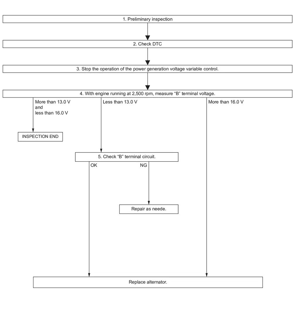
DETAILED FLOW
PRELIMINARY INSPECTION
Perform the preliminary inspection. Refer to Inspection Procedure.
>>
GO TO 2.
CHECK FOR DTC
Perform self diagnosis with CONSULT.
Is applicable DTC detected?
YES-1>>B12A4-81: Refer to DTC Description.
YES-2>>B12A4-92: Refer to DTC Description.
YES-3>>Other than above: Refer to DTC Index.
NO>>GO TO 3.
STOP POWER GENERATION VOLTAGE VARIABLE CONTROL SYSTEM
>>
GO TO 4.
MEASURE “B� TERMINAL VOLTAGE
Start engine. With engine running at 2,500 rpm, measure “B� terminal voltage.
What voltage does the measurement result show?
More than 13.0 V and less than 16.0 V>>INSPECTION END
Less than 13.0 V>>GO TO 5.
More than 16.0 V>>Replace alternator. Refer to Removal and Installation.
“B� TERMINAL CIRCUIT INSPECTION
Check “B� terminal circuit. Refer to Diagnosis Procedure.
Is the inspection result normal?
OK>>Replace alternator. Refer to Removal and Installation.
NG>>Repair as needed.
Other materials
Condenser Outlet Pipe
Removal and Installation
REMOVALCAUTION:
Perform lubricant return operation before each refrigeration system disassembly. However, if a large amount of refrigerant or lubricant leak is detected, never perform lubricant return operation. Refer to Perform Lubricant Return Operation.
When disconnec ...
Rear Rh Side Power Window Does Not Operate
When Both Power Window Main Switch and Rear Power Window Switch Rh Are Operated
Diagnosis Procedure
CHECK REAR POWER WINDOW MOTOR RH POWER SUPPLY AND GROUND CIRCUIT
Check rear power window motor RH power supply and ground circuit. Refer to Diagnosis Procedure.
Is the inspection result normal?
YES ...
Nissanconnect Tools and Preparation
Preparation
Commercial Service Tools
Tool name Description
Power tool
Loosening screws
...