
Nissan Armada 2025-2026 Service and Repair Manual: Inspection
CRANKSHAFT END PLAY
Measure the clearance between thrust bearings and crankshaft arm when crankshaft is moved fully forward or backward with a dial indicator.
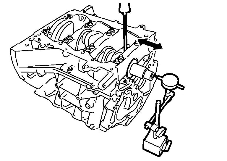
Standard and limit : Refer to CylinderBlock. If the measured value exceeds the limit, replace thrust bearings, and measure again. If it still exceeds the limit, replace crankshaft also.
CONNECTING ROD SIDE CLEARANCE
Measure the side clearance between connecting rod and crankshaft arm with a feeler gauge (commercial service tool).
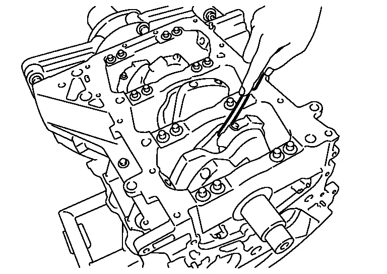
Standard and limit : Refer to CylinderBlock. If the measured value exceeds the limit, replace connecting rod, and measure again. If it still exceeds the limit, replace crankshaft also.
PISTON TO PISTON PIN OIL CLEARANCE
Piston Pin Hole Diameter
Measure the inner diameter of piston pin hole with an inside micrometer (A).
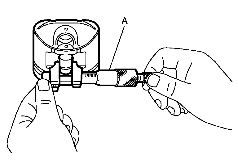
| Standard | : Refer to CylinderBlock. |
Piston Pin Outer Diameter
Measure the outer diameter of piston pin with a micrometer (A).
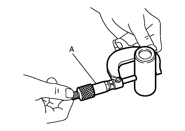
| Standard | : Refer to CylinderBlock. |
Piston to Piston Pin Oil Clearance
(Piston to piston pin oil clearance) = (Piston pin hole diameter) – (Piston pin outer diameter)
| Standard | : Refer to CylinderBlock. |
If the calculated value is out of the standard, replace piston and piston pin assembly.
When replacing piston and piston pin assembly, Refer to ConnectingRodBearing.
 NOTE:
NOTE:Piston is available together with piston pin as assembly.
PISTON RING SIDE CLEARANCE
Measure the side clearance of piston ring
 and piston ring groove with a feeler gauge (commercial service tool) (C).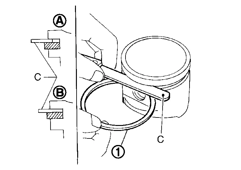

: NG 
: OK Standard and limit : Refer to CylinderBlock. If the measured value exceeds the limit, replace piston ring, and measure again. If it still exceeds the limit, replace piston also.
PISTON RING END GAP
Check that the cylinder bore inner diameter is within the specification. Refer to Disassembly and Assembly.
Lubricate with new engine oil to piston
and piston ring  , and then insert piston ring until middle of cylinder with piston, and measure the piston ring end gap with a feeler gauge (commercial service tool) (B).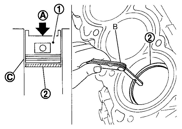
: Press-fit 
: Measuring point Standard and limit : Refer to CylinderBlock. If the measured value exceeds the limit, replace piston ring, and measure again.
CONNECTING ROD BEND AND TORSION
Check with a connecting rod aligner.
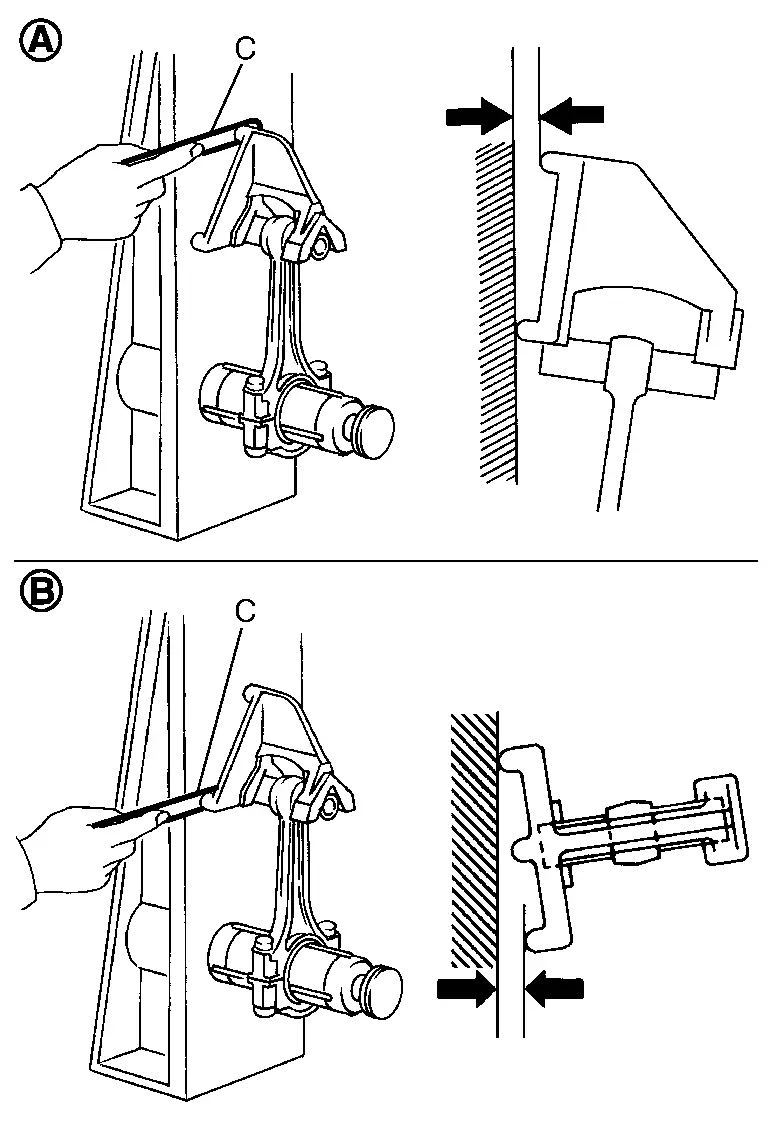
: Bend : Torsion C : Feeler gauge (commercial service tool) Bend limit : Refer to CylinderBlock. Torsion limit If it exceeds the limit, replace connecting rod assembly.
CONNECTING ROD BIG END DIAMETER
Install connecting rod bearing cap without installing connecting rod bearing, and tighten connecting rod bolts to the specified torque. Refer to Disassembly and Assembly for the tightening procedure.
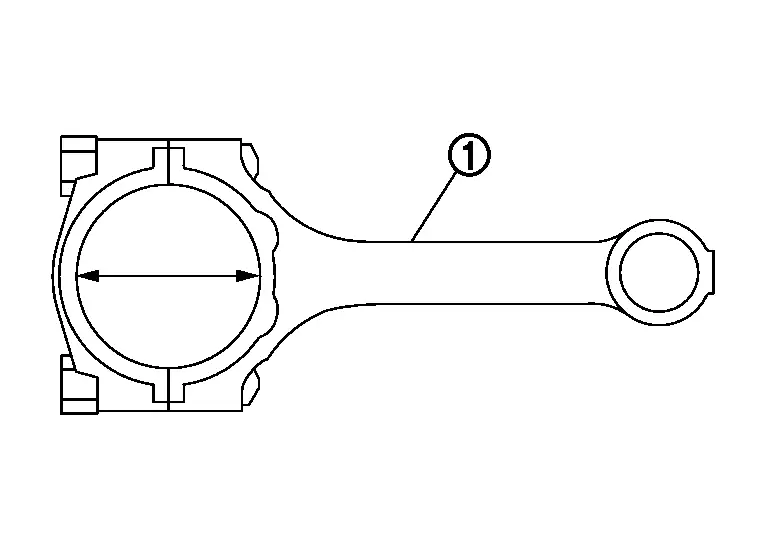
: Connecting rod Measure the inner diameter of connecting rod big end with an inside micrometer.
Standard : Refer to CylinderBlock. If out of the standard, replace connecting rod assembly.
CONNECTING ROD BUSHING OIL CLEARANCE
Connecting Rod Bushing Inner Diameter
Measure the inner diameter of connecting rod bushing with an inside micrometer (A).
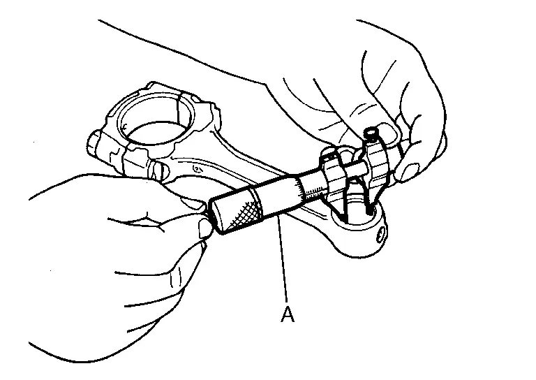
| Standard | : Refer to CylinderBlock. |
Piston Pin Outer Diameter
Measure the outer diameter of piston pin with a micrometer (A).
| Standard | : Refer to CylinderBlock. |
Connecting Rod Bushing Oil Clearance
(Connecting rod bushing oil clearance) = (Connecting rod bushing inner diameter) – (Piston pin outer diameter)
| Standard and limit | : Refer to CylinderBlock. |
If the calculated value exceeds the limit, replace connecting rod assembly and/or piston and piston pin assembly.
If replacing piston and piston pin assembly, refer to ConnectingRodBearing.
If replacing connecting rod assembly, refer to ConnectingRodBearing to select the connecting rod bearing.
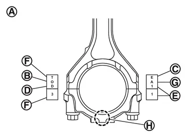
: Sample codes : Small-end diameter grade : Big-end diameter grade 
: Weight grade 
: Cylinder No. 
: Management code 
: Management code
Factory installed parts grading:
Service parts apply only to grade “0�.
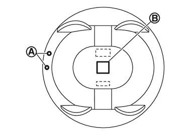
: Front mark : Two dimensional code Unit: mm (in)
Connecting rod bushing inner diameter * 23.000 - 23.006
(0.9055 - 0.9057)Piston pin hole diameter 22.995 - 22.999
(0.9053 - 0.9055)Piston pin outer diameter 22.989 - 22.993
(0.9051 - 0.9052)*: After installing in connecting rod
CYLINDER BLOCK DISTORTION
Using a scraper, remove gasket on the cylinder block surface, and also remove engine oil, scale, carbon, or other contamination.
CAUTION:
Never allow gasket flakes to enter engine oil or engine coolant passages.
Measure the distortion on the cylinder block upper face at some different points in six directions
, , , , and  with a straightedge (A) and a feeler gauge (commercial service tool) (B).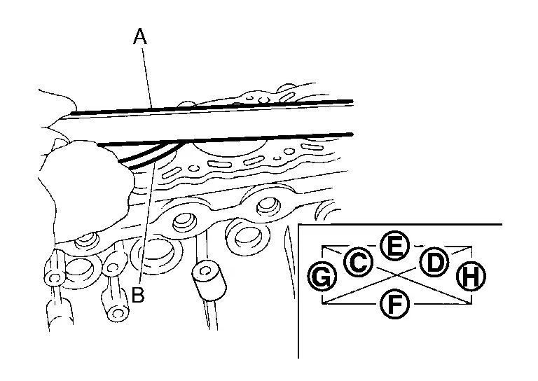
Limit : Refer to CylinderBlock. If it exceeds the limit, replace cylinder block.
MAIN BEARING HOUSING INNER DIAMETER
Install lower cylinder block
without installing main bearings, and tighten lower cylinder block bolts to the specified torque. Refer to Disassembly and Assembly for the tightening procedure.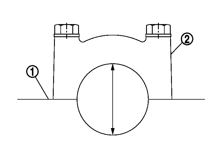
Measure the inner diameter of main bearing housing with a bore gauge.
Standard : Refer to CylinderBlock. If out of the standard, replace cylinder block
and lower cylinder block as assembly.NOTE:Cylinder block cannot be replaced as a single part, because it is machined together with lower cylinder block.
PISTON TO CYLINDER BORE CLEARANCE
Cylinder Bore inner Diameter
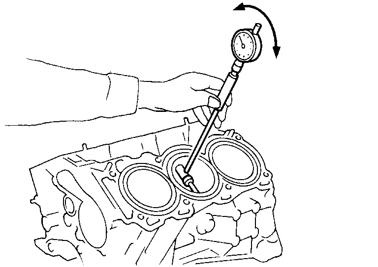
Using a bore gauge, measure cylinder bore for wear, out-of-round and taper at six different points on each cylinder.
and directions at , and is in longitudinal direction of engine.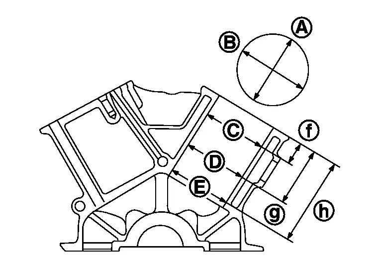

: 10 mm (0.39 in) 
: 60 mm (2.36 in) 
: 125 mm (4.92 in) Standard and limit : Refer to CylinderBlock. If the measured value exceeds the limit, or if there are scratches and/or seizure on the cylinder inner wall, hone or rebore the inner wall.
Piston Skirt Diameter
Measure the outer diameter of piston skirt with a micrometer (A).
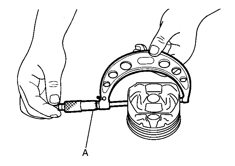
| Measure point | : Refer to CylinderBlock. |
| Standard |
Piston-to-Cylinder Bore Clearance
Calculate by piston skirt diameter and cylinder bore inner diameter [direction , position ].
| : Direction |
| : Position |
| : Position |
| : 10 mm (0.39 in) |
| : 60 mm (2.36 in) |
| : 125 mm (4.92 in) |
(Clearance) = (Cylinder bore inner diameter) – (Piston skirt diameter).
| Standard and limit | : Refer to CylinderBlock. |
If the calculated value exceeds the limit, replace piston and piston pin assembly. Refer to CylinderBlock.
Reboring Cylinder Bore
Cylinder bore size is determined by adding piston to cylinder bore clearance to piston skirt diameter.
| Re-bored size calculation: D = A + B – C | |
| where, | |
| A: Piston skirt diameter as measured | |
| B: Piston to cylinder bore clearance (standard value) | |
| C: Honing allowance 0.02 mm (0.0008 in) | |
| D: Bored diameter | |
Install lower cylinder block, and tighten to the specified torque. Otherwise, cylinder bores may be distorted in final assembly.
Cut cylinder bores.
NOTE:
When any cylinder needs boring, all other cylinders must also be bored.
Do not cut too much out of cylinder bore at a time. Cut only 0.05 mm (0.0020 in) or so in diameter at a time.
Hone cylinders to obtain the specified piston to cylinder bore clearance.
Measure finished cylinder bore for the out-of-round and taper.
NOTE:
Perform measurement after cylinder bore cools down.
CRANKSHAFT MAIN JOURNAL DIAMETER
Measure the outer diameter of crankshaft main journals with a micrometer.
Standard : Refer to CylinderBlock. If out of the standard, measure the main bearing oil clearance. Then use undersize bearing. Refer to Main Bearing.
CRANKSHAFT PIN JOURNAL DIAMETER
Measure the outer diameter of crankshaft pin journal with a micrometer (A).
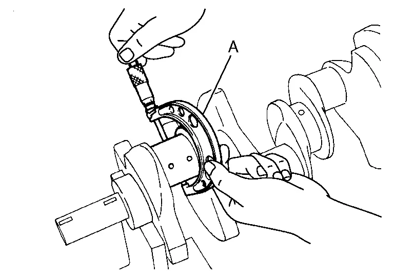
Standard : Refer to CylinderBlock. If out of the standard, measure the connecting rod bearing oil clearance. Then use undersize bearing. Refer to ConnectingRodBearing.
CRANKSHAFT OUT-OF-ROUND AND TAPER
Measure the dimensions at four different points as shown in the figure on each main journal and pin journal with a micrometer.
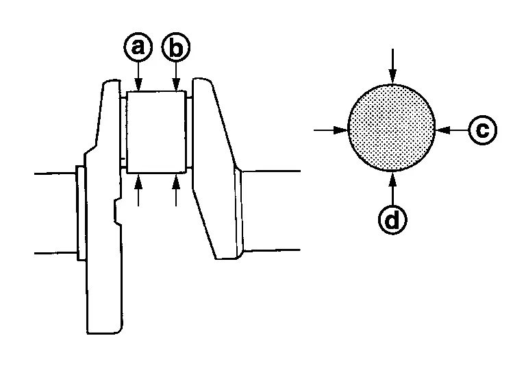
Out-of-round is indicated by the difference in the dimensions between
 and
and  at
at  and
and  .
.Taper is indicated by the difference in the dimensions between
and direction, and position.Limit : Refer to CylinderBlock. If the measured value exceeds the limit, correct or replace crankshaft.
If corrected, measure the bearing oil clearance of the corrected main journal and/or pin journal. Then select the main bearing and/or connecting rod bearing. Refer to Main Bearing and/or ConnectingRodBearing.
CRANKSHAFT RUNOUT
Place V-block on precise flat table, and support the journals on both ends of crankshaft.
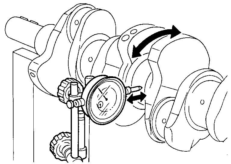
Place a dial indicator straight up on the No. 3 journal.
While rotating crankshaft, read the movement of the pointer on a dial indicator. (Total indicator reading)
Standard and limit : Refer to CylinderBlock. If it exceeds the limit, replace crankshaft.
CONNECTING ROD BEARING OIL CLEARANCE
Method by Calculation
Install connecting rod bearings
to connecting rod and connecting rod cap, and tighten connecting rod bolts to the specified torque. Refer to Disassembly and Assembly for the tightening procedure.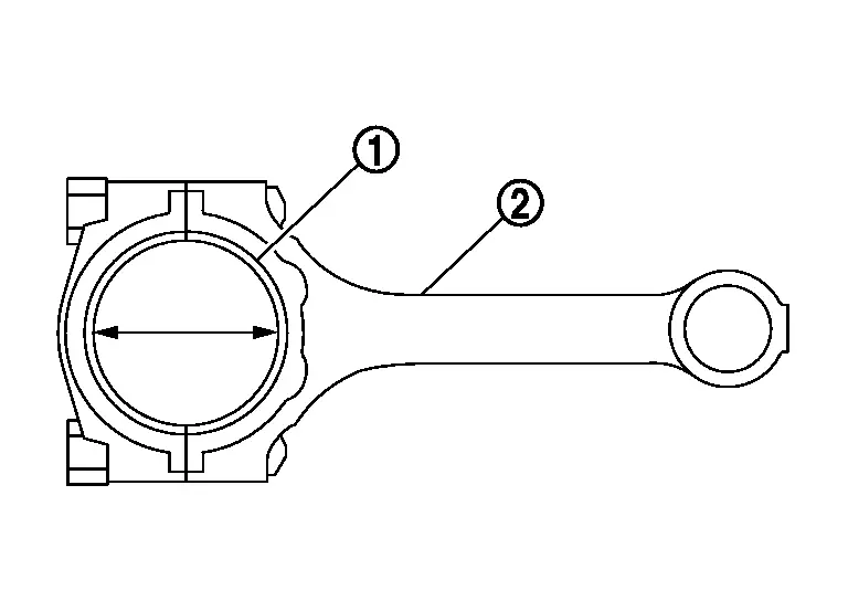
Measure the inner diameter of connecting rod bearing with an inside micrometer.
(Oil clearance) = (Connecting rod bearing inner diameter) – (Crankshaft pin journal diameter)
| Standard and limit | : Refer to ConnectingRodBearing. | |
If the calculated value exceeds the limit, select proper connecting rod bearing according to connecting rod big end diameter and crankshaft pin journal diameter to obtain the specified bearing oil clearance. Refer to ConnectingRodBearing.
Method of Using Plastigage
Remove oil and dust on crankshaft pin journal and the surfaces of each bearing completely.
Cut a plastigage slightly shorter than the bearing width, and place it in crankshaft axial direction, avoiding oil holes.
Install connecting rod bearings to connecting rod and connecting rod bearing cap, and tighten connecting rod bolts to the specified torque. Refer to Disassembly and Assembly for the tightening procedure.
CAUTION:
Never rotate crankshaft.
Remove connecting rod bearing cap and bearings, and using the scale on the plastigage bag, measure the plastigage width.
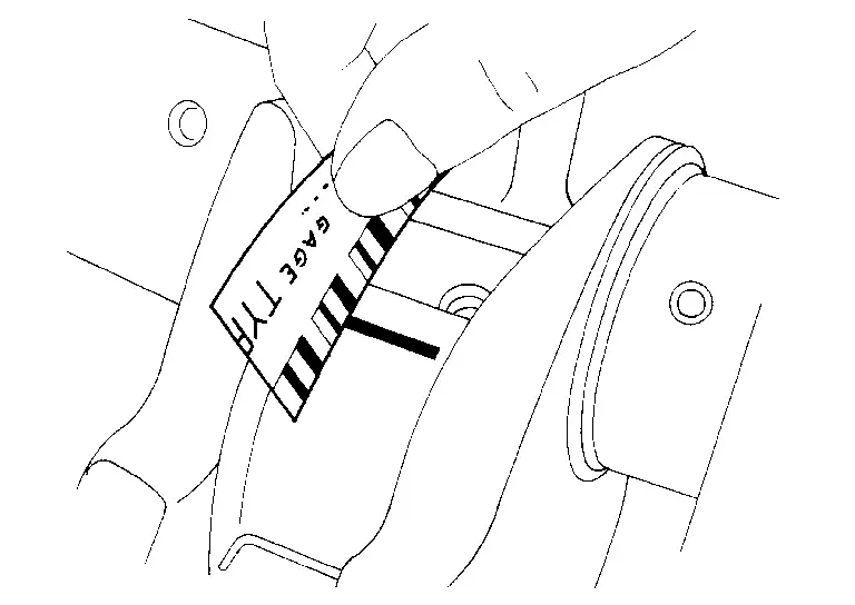 NOTE:
NOTE:The procedure when the measured value exceeds the limit is the same as that described in the “Method by Calculation�.
MAIN BEARING OIL CLEARANCE
Method by Calculation
Install main bearings
 to cylinder block and lower cylinder block , and tighten lower cylinder block bolts to the specified torque. Refer to Disassembly and Assembly for the tightening procedure.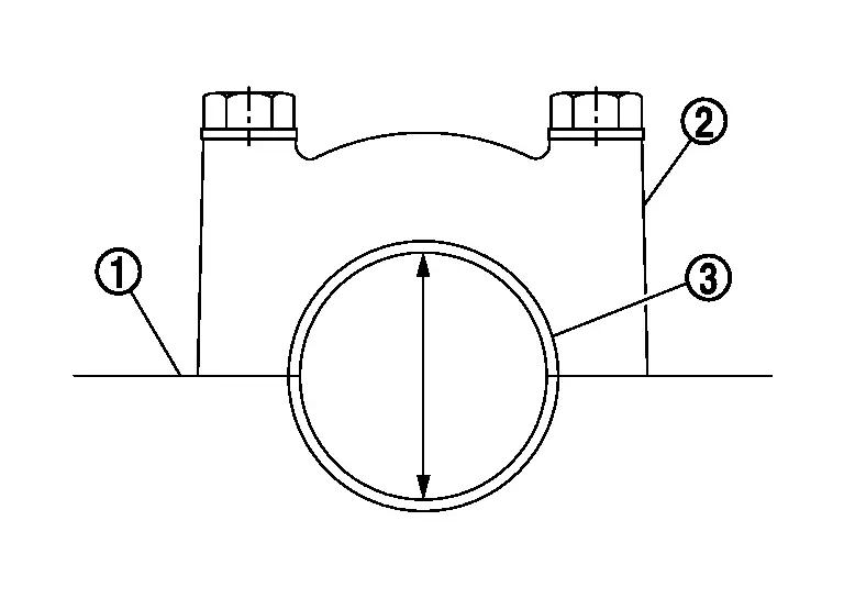
Measure the inner diameter of main bearing with a bore gauge.
(Oil clearance) = (Main bearing inner diameter) – (Crankshaft main journal diameter)
| Standard and limit | : Refer to Main Bearing. | |
If the calculated value exceeds the limit, select proper main bearing according to main bearing inner diameter and crankshaft main journal diameter to obtain the specified bearing oil clearance. Refer to ConnectingRodBearing.
Method of Using Plastigage
Remove engine oil and dust on crankshaft journal and the surfaces of each bearing completely.
Cut a plastigage slightly shorter than the bearing width, and place it in crankshaft axial direction, avoiding oil holes.
Install main bearing to cylinder block and lower cylinder block, and tighten lower cylinder block bolts with lower cylinder block to the specified torque. Refer to Disassembly and Assembly for the tightening procedure.
CAUTION:
Never rotate crankshaft.
Remove lower cylinder block and bearings, and using the scale on the plastigage bag, measure the plastigage width.
NOTE:The procedure when the measured value exceeds the limit is the same as that described in the “Method by Calculation�.
MAIN BEARING CRUSH HEIGHT
When lower cylinder block is removed after being tightened to the specified torque with main bearings
installed, the tip end of bearing must protrude. Refer to Disassembly and Assembly for the tightening procedure.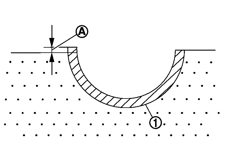
: Crush height Standard : There must be crush height. If the standard is not met, replace main bearings.
CONNECTING ROD BEARING CRUSH HEIGHT
When connecting rod bearing cap is removed after being tightened to the specified torque with connecting rod bearings
installed, the tip end of bearing must protrude. Refer to Disassembly and Assembly for the tightening procedure.: Crush height Standard : There must be crush height. If the standard is not met, replace connecting rod bearings.
LOWER CYLINDER BLOCK BOLT OUTER DIAMETER
Measure the outer diameters
, at two positions as shown in the figure.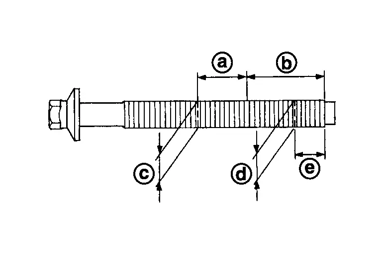
: 20 mm (0.79 in) : 30 mm (1.18 in) 
: 10 mm (0.39 in) If reduction appears in
range, regard it .Limit [ – ] : 0.11 mm (0.0043 in) If it exceeds the limit (large difference in dimensions), replace lower cylinder block bolt with new one.
CONNECTING ROD BOLT OUTER DIAMETER
Measure the outer diameters [, and ] at the position shown in the figure.
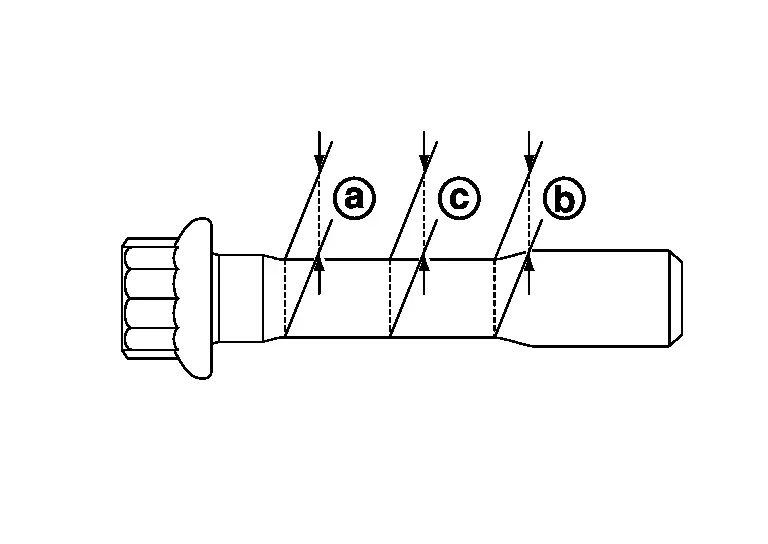
| : Value at the end of the smaller diameter of the bolt |
| : Value at the end of the smaller diameter of the bolt [opposite side of ] |
| : Value of the smallest diameter of the smaller of the bolt |
Obtain a mean value of and .
Subtract from .
| Limit [ – ] | : 0.09 mm (0.0035 in) |
If it exceeds the limit (large difference in dimensions), replace the bolt with new one.
OIL JET
Check nozzle for deformation and damage.
Blow compressed air from nozzle, and check for clogs.
If it is not satisfied, clean or replace oil jet.
OIL JET RELIEF VALVE
Using a clean plastic stick, press check valve in oil jet relief valve. Check that valve moves smoothly with proper reaction force.
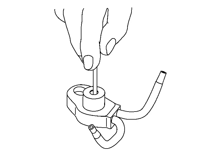
If it is not satisfied, replace oil jet relief valve.
 Disassembly and Assembly
DISASSEMBLY
Remove the following parts:
Oil pan (lower): Refer to Removal and Installation.
Oil pan (upper): Refer to Disassembly and Assembly.
Timing chain: Refer to Removal and Installation.
Cylin ...
 Piston
DESCRIPTION
Selection points Selection parts Selection items Selection methods Between cylinder block and crankshaft Main bearing Main bearing grade
(bearing thickness) Determined by match of c ...
Other materials:
Symptom Table
Perform “Data Monitor� of CONSULT to check for any malfunctioning item.
Check that the data monitor display switches in conjunction with the combination switch operation.
If there is a switch whose display does not change, specify the applicable combination switch circuit (INPUT 1 - 6 and OUTPUT ...
Hammering
Elongation of aluminum alloy during hammering will be greater than with steel plates. Therefore, a wooden or plastic hammer should be used with a softer blow to prevent stretching and work hardening of panels. Observe the following in case body filler is applied after hammering.
Apply wash primer a ...
Inspection
INSPECTION AFTER REMOVAL
Appearance
Propeller Shaft Runout
Check propeller shaft runout at several points with a dial indicator. If runout exceeds specifications, replace propeller shaft assembly.
Propeller shaft runout : Refer to Propeller Shaft Tube.
Propeller shaft runout measuring point (Poi ...

0.0065