
Nissan Armada 2025-2026 Service and Repair Manual: Disassembly and Assembly
DISASSEMBLY
CAUTION:
Disassemble and assemble steering gear assembly by fixing the mounting area with a vise using copper plates.
Loosen outer socket lock nut, and remove outer socket.
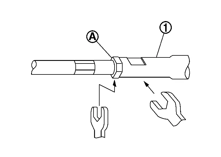
CAUTION:
To prevent damage, hold outer socket  across flats using suitable tool while loosening outer socket lock nut
  .
.
Remove boot clamps, and then remove boot from inner socket and housing.
CAUTION:
Never damage inner socket part of gear housing assembly when removing boot. Steering gear assembly must be replaced if gear housing assembly are damaged because it may cause foreign material interfusion.
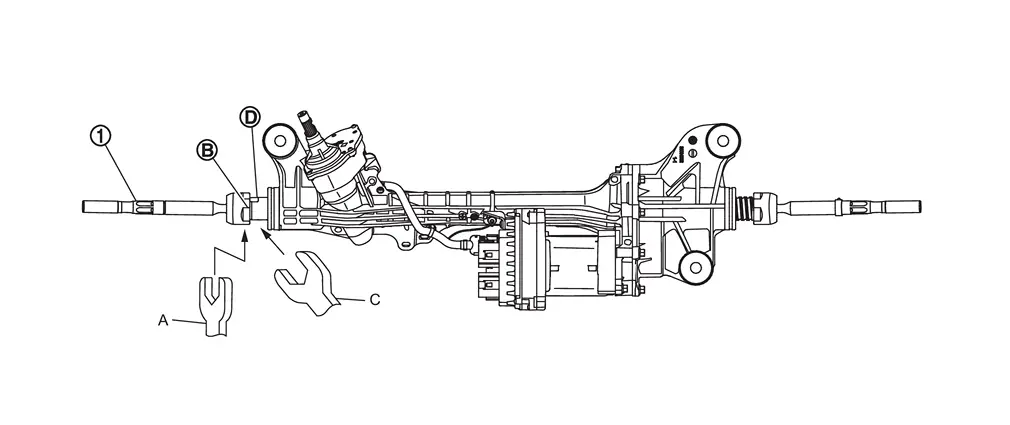
Remove the left inner socket.
CAUTION:
To prevent damage to the steering gear when removing the inner socket , hold suitable tool (C) across steering gear flats  while turning suitable tool (A) across inner socket flats
  .
.
Remove the right inner socket.
CAUTION:
To prevent damage to the steering gear when removing the inner socket
, hold suitable tool (C) across steering gear flats while turning suitable tool (A) across inner socket flats .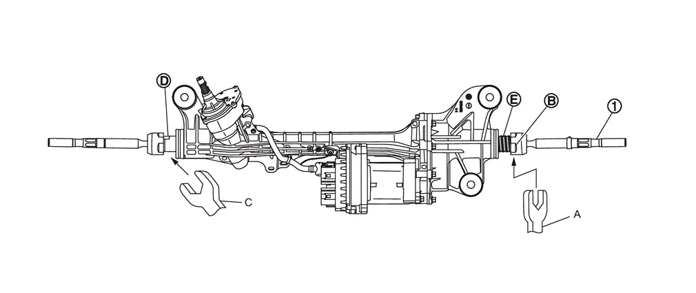
Never remove the inner socket by fixing part
 with a suitable tool.
Perform inspection after disassembly. Refer to Inspection.
ASSEMBLY
Install left inner socket. Tighten to specified torque. Refer to Exploded View.
CAUTION:
To prevent damage to the steering gear when installing the inner socket , hold suitable tool (C) across steering gear flats while turning suitable tool (A) across inner socket flats .
Install right inner socket. Tighten to specified torque. Refer to Exploded View.
CAUTION:
To prevent damage to the steering gear when installing the inner socket
, hold suitable tool (C) across steering gear flats while turning suitable tool (A) across inner socket flats .Never install the inner socket by fixing part
with a suitable tool.
Apply recommended grease to part of inner socket.
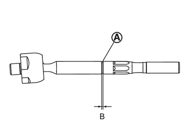
| Use RheoGel TEK676. | |
| B (groove part) | : 0.2 mm (0.008 in) |
Apply recommended grease to part of gear housing assembly.
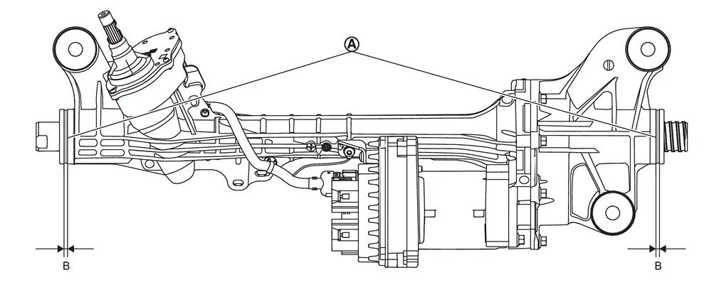
| Use RheoGel TEK676. | |
| B | : 4 mm (0.16 in) |
Install boot to inner socket and gear housing.
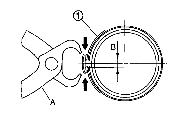
Install boot clamp (large diameter) to boot using boot band crimping tool [SST: KV40107300 (NI-51751)] (A).
CAUTION:
Never reuse boot clamp (large diameter).
Install boot clamp (large diameter) securely to boot groove, and crimp it so as to have clearance (B) of 5 mm (0.20 in) or less as shown.
Install boot clamp (small diameter) to boot.
CAUTION:
Never reuse boot clamp (small diameter).
Adjust inner socket to standard length (A), and then tighten lock nut to the specified torque. Check length again after tightening lock nut.
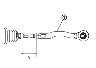
| : Outer socket |
| Inner socket length (A) | : Steering Gear and Linkage |
CAUTION:
When tightening the lock nut
, be sure to fix outer socket with a wrench or an equivalent to prevent the ball joint from getting contact with the knuckle.Adjust toe-in after this procedure. The length achieved after toe-in adjustment is not necessarily the above value.
 Removal and Installation
WARNING:
CAUTION:
Never disconnect or pull the torque sensor harness and harness connector .
REMOVAL
Set vehicle to the straight-ahead position.
Remove 12V battery terminal. Refer to Removal and Ins ...
 Inspection
INSPECTION AFTER DISASSEMBLY
Boot
Check boot for cracks, and replace it if a malfunction is detected.
Gear Housing Assembly
Check gear housing assembly for damage and scratches. Replace if there are ...
Other materials:
Work Procedure
After the front camera unit or distance sensor are replaced or a problem with ProPILOT Assist is corrected, perform a test of ProPILOT Assist 1.1 operation and check that ProPILOT Assist 1.1 operates correctly.
CAUTION:
Always drive safely when performing the action test.
CHECK FOR ProPILOT ASSIST S ...
Removal and Installation
WARNING:
REMOVAL
Remove air breather hose A from transfer assembly.
Remove clip A .
Remove clip B .
Remove A/T air breather hose. Refer to Removal and Installation.
Release clip C and remove air breather hose assembly from bracket.
Separate each component part.
INSTALLATION
Note the follo ...
Removal and Installation
WARNING:
REMOVAL
Remove air breather hose A from transfer assembly.
Remove clip A .
Remove clip B .
Remove A/T air breather hose. Refer to Removal and Installation.
Release clip C and remove air breather hose assembly from bracket.
Separate each component part.
INSTALLATION
Note the follo ...

0.0058