
Nissan Armada 2025-2026 Service and Repair Manual: Removal and Installation
WARNING:
CAUTION:
Never disconnect or pull the torque sensor harness  and harness connector
  .
.
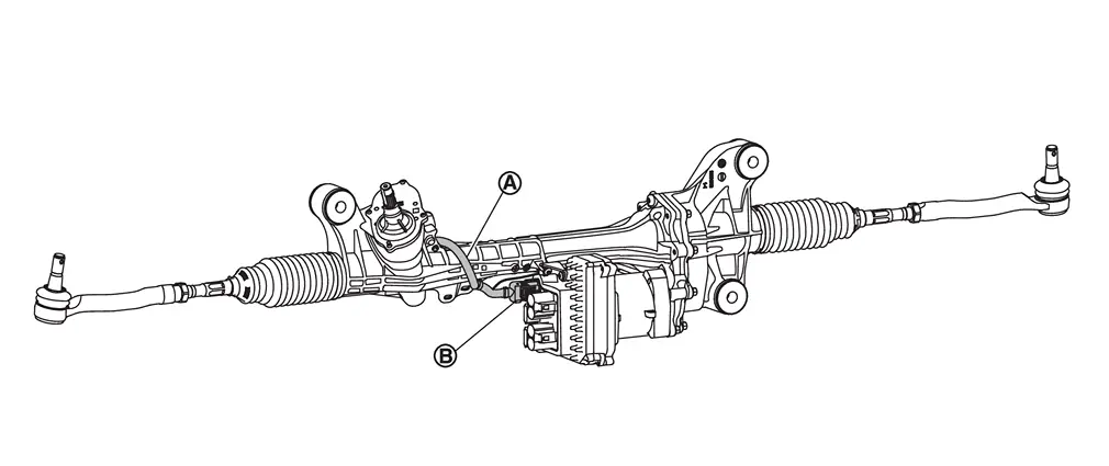
REMOVAL
Set vehicle to the straight-ahead position.
Remove 12V battery terminal. Refer to Removal and Installation.
Remove tires. Refer to ROAD WHEEL TIRE : Removal & Installation.
Remove cotter pins and mounting nuts, and separate outer socket from steering knuckle.
Remove outer sockets, outer socket lock nuts, boots, boot clamps, and Inner sockets if necessary. Refer to Disassembly and Assembly.
Remove front under cover. Refer to Removal and Installation.
Remove engine under cover. Refer to Removal and Installation.
Disconnect steering gear assembly harness connectors.
Remove harness clip from steering gear assembly.
Remove lower joint from steering gear assembly.
Remove air inlet tube 1. Refer to Removal & Installation.
Remove steering gear assembly mounting bolts and nuts.
Remove steering gear assembly from vehicle.
INSTALLATION
Note the following, and install in the reverse order of removal.
CAUTION:
Spiral cable may be cut if steering wheel turns while separating steering column assembly and steering gear assembly. Always fix the steering wheel using string to avoid turning.
Never damage the boot band when installing mounting bolts and nuts.
Before installation, check that the tilt position is at the middle level.
To install the steering gear assembly, after inserting the mounting bolts, temporarily tighten the mounting nuts using the tightening method and numerical order shown below, and then tighten to the specified torque.
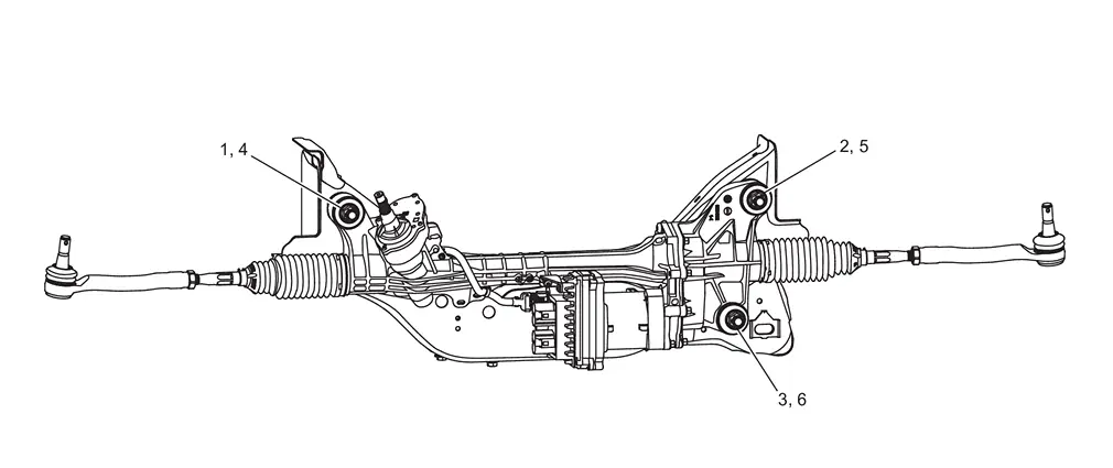
Temporary tightening : 1 → 2 → 3 Final tightening (Specified torque) : 4 → 5 → 6 Perform final tightening of nuts and bolts on each part under unladen conditions with tires on level ground when removing steering gear assembly. Check wheel alignment.
Rotate steering wheel to check for decentered condition, binding, noise or excessive steering effort.
Perform inspection after installation. Refer to Inspection.
 Exploded View
REMOVAL
Member Cotter pin Steering gear assembly : Vehicle front : N·m (kg-m, ft-lb) : Always replace after every disassembly.
DISASSEMBLY
Outer socket Outer socket lock nut Boot clamp ...
 Disassembly and Assembly
DISASSEMBLY
CAUTION:
Disassemble and assemble steering gear assembly by fixing the mounting area with a vise using copper plates.
Loosen outer socket lock nut, and remove outer socket.
CAUTION:
To p ...
Other materials:
Low Tire Pressure Warning Lamp Does Not Turn on
The low tire pressure warning lamp does not turn ON when the ignition switch is placed ON.
NOTE:
The low tire pressure warning lamp turn ON for approximately 1 second and then turns OFF when the ignition switch is placed ON. This is to check that no abnormal condition is present in the tire pressure ...
Inspection
INSPECTION AFTER REMOVAL
Appearance
Check the following items, and replace the part if necessary.
Suspension arm and bushing for deformation, cracks or damage.
Boot of ball joint for cracks or damage, and also for grease leakage.
Ball Joint Inspection
Manually move ball stud to confirm it moves smo ...
Work Flow
WORK FLOW
STEP DESCRIPTION STEP 1 Get detailed information about the conditions and the environment when the incident occurred.
The following are key pieces of information required to make a good analysis: WHAT Vehicle Model, Engine, Transmission/Transaxle and the System (i.e. Radio). WHEN D ...

0.0059