Exploded View
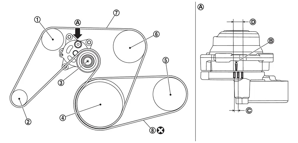
 |
Idler pulley |  |
Alternator |  |
Drive belt auto-tensioner |
 |
Crankshaft pulley |  |
A/C compressor |  |
Water pump |
 |
Drive belt |  |
A/C compressor belt | ||
 |
View |  |
Indicator |  |
Range when new drive belt is installed |
 |
Possible use range | ||||
 |
Always replace after every disassembly. |
Adjustment
Refer to Drive Belt.
Inspection
WARNING:
-
Jacking up or lift up the vehicle may the vehicle height to go down which cause a personal injury and/or damage to the air suspension component parts. Refer to Precaution for when Jacking and Lifting Up the vehicle with Electronic Air Suspension System.
INSPECTION BEFORE REMOVAL
Drive belt
WARNING:
Be sure to perform the this step when engine is stopped.
-
Check that the indicator (notch on fixed side) of drive belt auto-tensioner is within the possible use range.
 NOTE:
NOTE:
Check the drive belt auto-tensioner indication when the engine is cold.
-
Visually check the entire drive belt for wear, damage or crack.
-
If the indicator (notch on fixed side) is out of the possible use range or belt is damaged, replace drive belt.
A/C compressor belt
WARNING:
Perform this step when engine is stopped.(30 min or longer after engine is stopped)
-
Visually check entire drive belt for wear, damage or cracks.
-
Using a tensiometer and confirm belt tension or vibration frequency value.
NOTE:
Before measuring, turn crankshaft pulley twice.
-
Measure belt
tension at " " points. (Both side measurement are correct)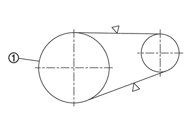
-
Confirm the belt tension value or the vibration frequency value. (see table below)
Belt tension Frequency 580 - 1327 N 192 - 292 Hz
INSPECTION AFTER INSTALLATION
Drive belt
-
Turn crankshaft pulley clockwise several times to equalize tension between each pulley, and then confirm tension of drive belt at indicator (notch on fixed side) is within the possible use range. Refer to Exploded View.
Other materials
Rear Blower Motor
Exploded View
Rear A/C unit assembly
Rear blower motor
: vehicle front
Removal and Installation
REMOVALRemove rear A/C unit assembly. Refer to Removal and Installation.
Disconnect rear blower unit harness connector.
Remove fixing screws , and then remove rear blower motor. ...
Glove Box Lid Lock Cylinder
Exploded View
Glove box assembly
Sleeve
Glove box lid lock cylinder
Removal and Installation
REMOVAL NOTE:
Glove box lid lock key cylinder is integrated with glove box assembly. So, glove box lid lock key cylinder cannot be removed from glove box assembly and it cannot be replaced without ...
Additional Service When Replacing Head up Display Unit
Work Procedure
DescriptionWhen replacing or removing the Head Up Display unit, distortion calibration of the display and adjustment of the display position are required.Work ProcedureREPLACE HEAD UP DISPLAY UNIT
Replace Head Up Display unit. Refer to Removal and Installation.
>>
GO TO 2.
PER ...