With Tail Lamp
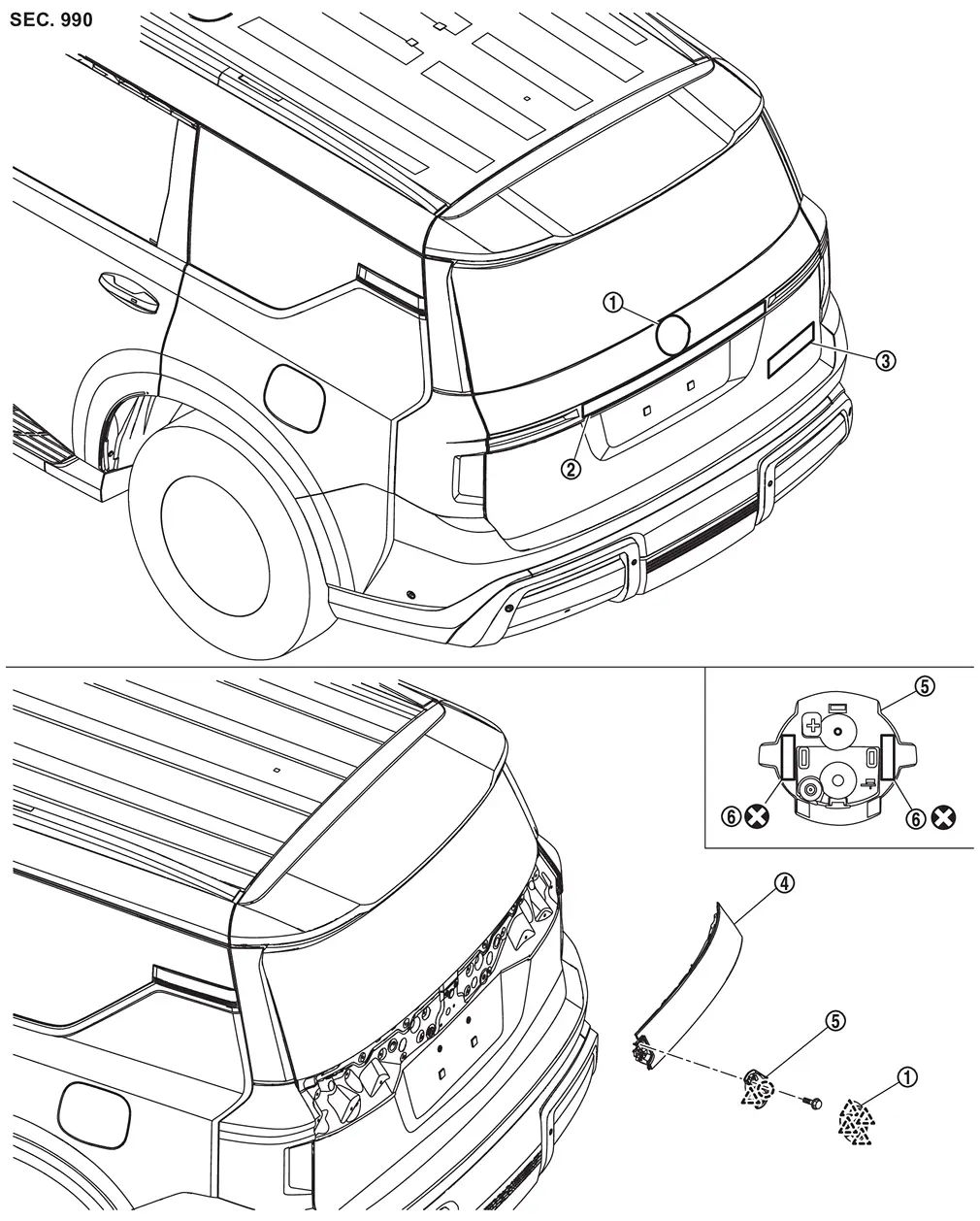
Exploded View
 |
Rear emblem |  |
Emblem A |  |
Emblem B |
 |
Tail lamp RH |  |
Rear emblem bracket |  |
Double-sided tape [t: 1.2 mm (0.047 in)] |
 |
: Clip | ||||
 |
: Pawl | ||||
 |
: Always replace after every disassembly. | ||||
Removal and Installation
REMOVAL
Apply protective tape (A) on the part to protect it from damage.
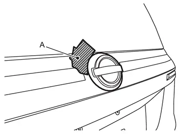
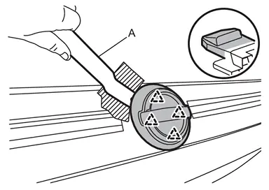
Disengage fixing pawls using remover tool (A), and then remove emblem A.
|
: Pawl |
Remove emblem bracket mounting bolt.
Apply protective tapes (A) on the part to protect it from damage.
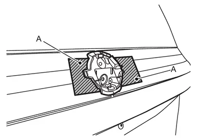
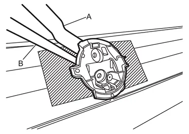
Cut double-sided tapes using remover tool (A) and cutter (B).
Disengage fixing pawl and clip using a remover tool (A), and then remove rear emblem bracket.
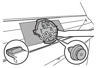
|
: Clip |
|
: Pawl |
Remove emblem A from back door finisher while warming using an industrial dryer.
CAUTION:
Never damage the painted surface of the back door finisher when removing.
Remove emblem B from the panel while warming using an industrial dryer.
CAUTION:
Never damage the painted surface of the panel when removing.
INSTALLATION
Note the following items, and then install in the reverse order of removal.
CAUTION:
-
Always replace double-sided tape with a new one, if rear emblem bracket is reused.
-
Degrease rear emblem bracket mounting surface of tail lamp RH.
-
Never wash the vehicle within 24 hours after installing so as to keep adhesive.
-
If paint bumps, dust, etc., adhere to the emblem mounting surface, it may cause a defective appearance.
-
Never reuse the emblem A and emblem B which was peeled.
 NOTE:
NOTE:
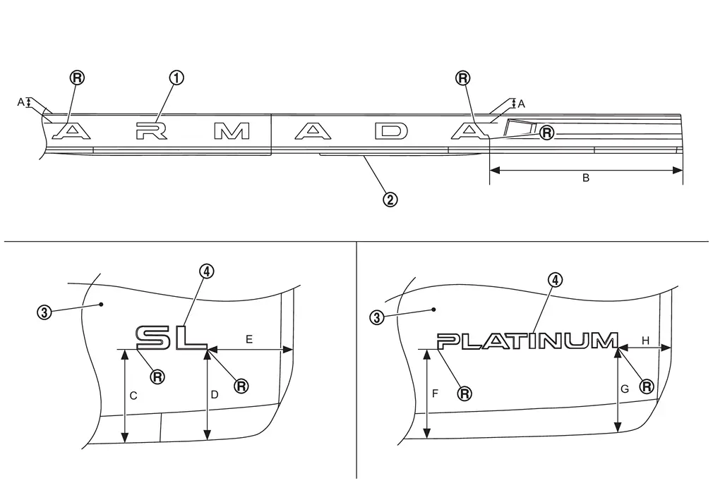
Refer to the figure below for the emblem A and emblem B mounting position.
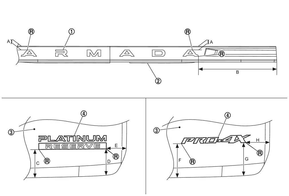
|
Emblem A | |
Back door finisher | |
Back door panel |
|
Emblem B | ||||
 |
: R end | ||||
| A | : 13.0 mm (0.512 in) | B | : 365.4 mm (14.386 in) | C | : 101.5 mm (3.996 in) |
| D | : 95.8 mm (3.772 in) | E | : 78.1 mm (3.075 in) | F | : 122.8 mm (4.835 in) |
| G | : 144.9 mm (5.705 in) | H | : 77.6 mm (3.055 in) |
Without Tail Lamp
Exploded View
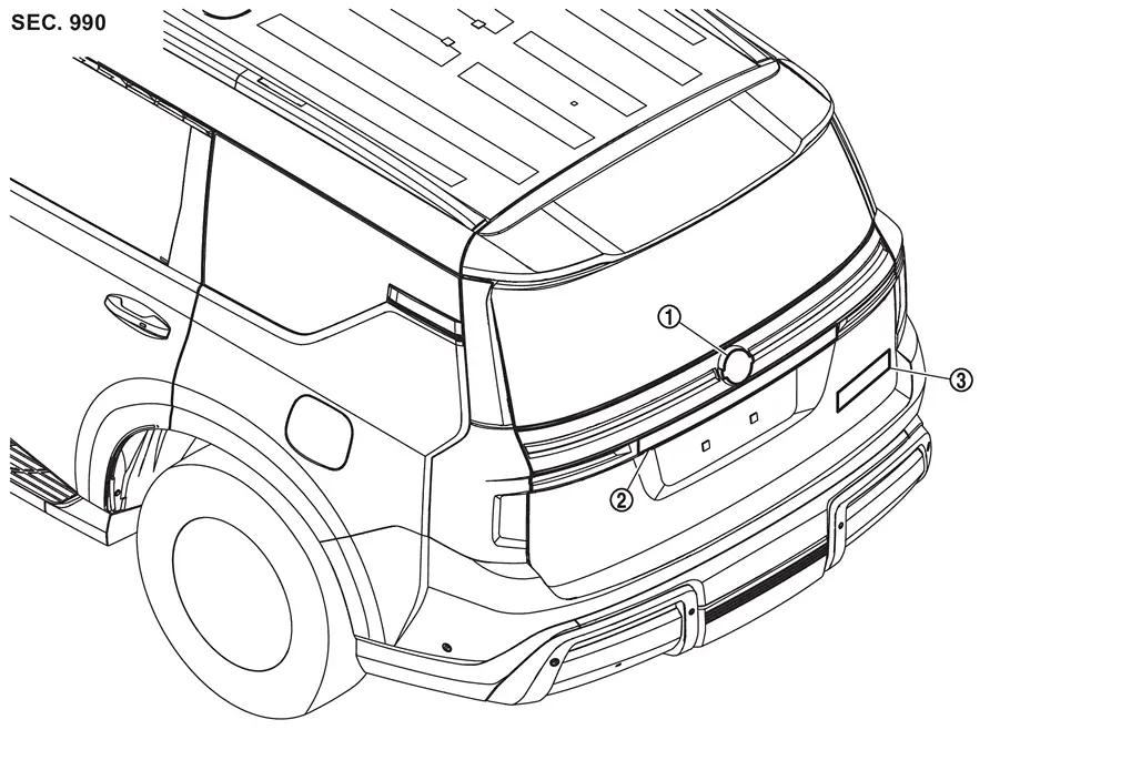
|
Emblem A | |
Emblem B | |
Emblem C |
Removal and Installation
REMOVAL
Remove emblem from the panel while warming using an industrial dryer.
CAUTION:
Never damage the painted surface of the panel when removing.
INSTALLATION
Note the following items, and then install in the reverse order of removal.
CAUTION:
-
Never reuse the emblem which was peeled.
-
Degrease the panel emblem mount.
-
If paint bumps, dust, etc., adhere to the emblem mounting surface, it may cause a defective appearance.
NOTE:
Refer to the figure below for the emblem B and emblem C mounting position.
|
Emblem B | |
Back door finisher | |
Back door panel |
|
Emblem C | ||||
|
: R end | ||||
| A | : 13.0 mm (0.512 in) | B | : 365.4 mm (14.386 in) | C | : 122.1 mm (4.807 in) |
| D | : 119.1 mm (4.689 in) | E | : 120.1 mm (4.728 in) | F | : 121.9 mm (4.799 in) |
| G | : 116.1 mm (4.571 in) | H | : 79.7 mm (3.138 in) |
Other materials
4wd Mode Does Not Change
Description
Vehicle does not enter 4-wheel drive mode even though 4WD warning turned to OFF.
Diagnosis Procedure
CHECK DTC OF TRANSFER CONTROL UNIT
With CONSULT
Ignition switch ON.
Perform self-diagnosis for “AWD/4WD�.
Is any DTC detected?
YES >>
Check DTC detected item. Refer to DT ...
Diagnosis and Repair Work Flow
Work Flow
OVERALL SEQUENCEDETAILED FLOWGET INFORMATION FOR SYMPTOM
Get detailed information from the customer about the symptom (the condition and the environment when the incident/malfunction occurs).
Check operation condition of the function that is malfunctioning.
>>
GO TO 2.
CHECK DTC
...
Driving Video Recorder Control Module
Removal and Installation
REMOVALCAUTION:
Before replacing driving video recorder control module, perform “ADDITIONAL SERVICE WHEN REPLACING DRIVING VIDEO RECORDER CONTROL MODULE�. For details, refer to Work Procedure.
Before replacing the driving video recorder control module, the customer s ...