Setting
 NOTE:
NOTE:
Explained here is how to disassemble with engine stand supporting transmission surface. When using a different type of engine stand, note the difference in the steps, etc.
Remove the engine assembly from the vehicle. Refer to Unit Removal & Installation.
Remove the parts that may restrict installation of engine to a widely use engine stand.
NOTE:
The procedure is described assuming that you use a widely use engine stand holding the surface, to which transmission is installed.
-
Fix crankshaft with a ring gear stopper [SST: KV10118600 (NI-48641)], and remove mounting bolts.
-
Loosen mounting bolts in diagonal order.
-
Check for deformation or damage of drive plate.
CAUTION:
-
Never disassemble drive plate.
-
Never place drive plate with signal plate facing down.
-
When handling signal plate, take care not to damage or scratch it.
-
Handle signal plate in a manner that prevents it from becoming magnetized.
-
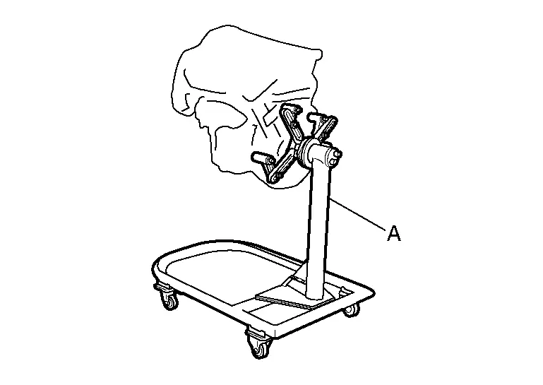
Lift the engine with hoist to install it onto the widely use engine stand.
CAUTION:
Use an engine stand that has a load capacity [220 kg (485 lb) or more] large enough for supporting the engine weight.
-
If the load capacity of the stand is not adequate, remove the following parts beforehand to reduce the potential risk of overturning the stand.
-
Remove intake manifold. Refer to Removal and Installation.
-
Remove fuel injector and fuel tube assembly. Refer to Removal and Installation.
-
Remove ignition coil. Refer to Removal and Installation.
-
Remove rocker cover. Refer to Removal and Installation.
-
Other removable brackets.
NOTE:
The figure shows an example of widely use engine stand (A) that can hold mating surface of transmission with drive plate removed.
CAUTION:
Before removing the hanging chains, check the engine stand is stable and there is no risk of overturning.
-
Drain engine oil. Refer to Draining.
Drain engine coolant by removing water drain plug  from both sides of the cylinder block as shown in the figure.
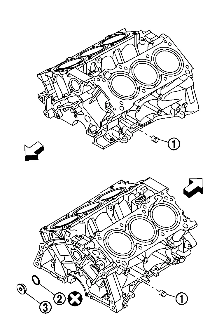
 |
: Washer |
 |
: Plug |
 |
: Always replace after every disassembly |
| : Engine front |
Other materials
Tire Pressure Monitoring System (TPMS)
Basic information
For optimal safety and performance of your Nissan Armada, each tire—including
the spare tire (if equipped)—should be inspected at least once a month when cold
and inflated according to the manufacturer’s recommended pressure values listed
on the vehicle placard or tire ...
4wd Tools and Preparation
Preparation
Special Service Tool
Tool number
(TechMate No.)
Tool name Description
KV40104001
(NI-53385)
Hub lock nut wrench
a: 85 mm (3.35 in)
b: 65 mm (2.56 in)
Removing and Installing wheel hub lock nut.
KV40107300
(NI-51751)
Boot band crimping tool
Installing boot band
KV401 ...
Driver Monitor Camera Control Unit
Exploded View
Driver monitor camera control unit
: N·m (kg-m, in-lb)
Removal and Installation
REMOVALRemove the front speaker grille. Refer to Removal and Installation.
Remove the mounting nuts, and remove the driver monitor camera control unit.
Disconnect the d ...