Exploded View
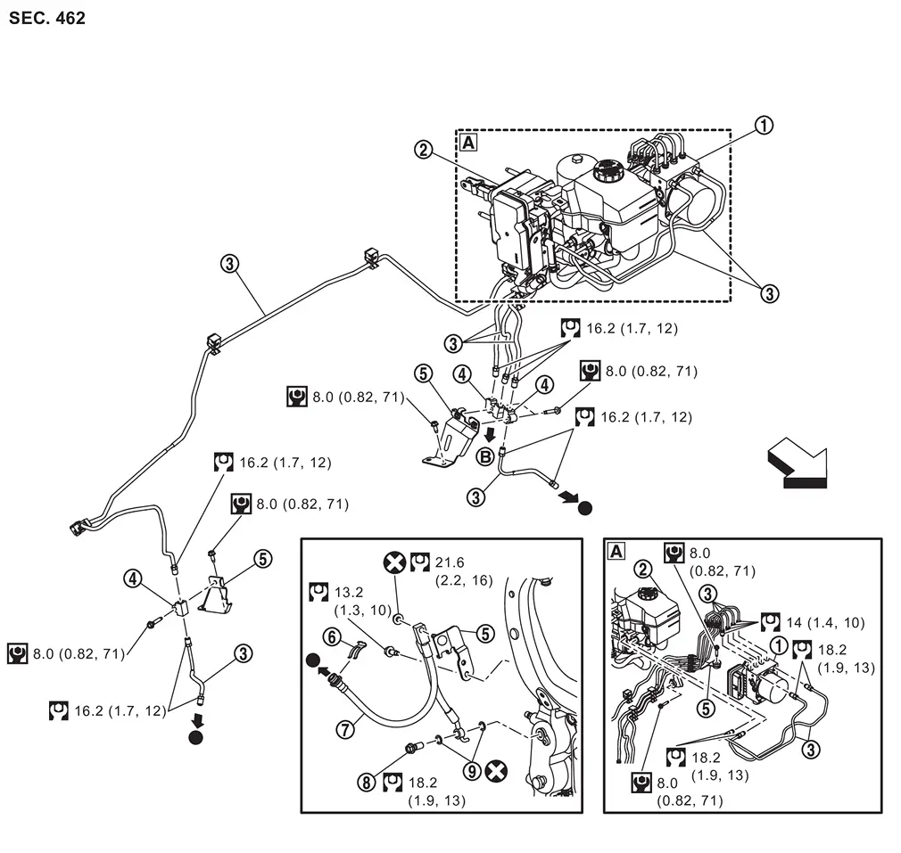
 |
ABS actuator and electric unit (control unit) |  |
Electrical brake control unit |  |
Brake tube |
 |
Connector |  |
Bracket |  |
Lock plate |
 |
Brake hose |  |
Union bolt |  |
Copper washer |
 |
To rear brake tube. Refer to Exploded View. | ||||
| : vehicle front | |||||
 |
: N·m (kg-m, ft-lb) | ||||
 |
: N·m (kg-m, in-lb) | ||||
 |
: Always replace after every disassembly. | ||||
 |
: Indicates that the part is connected at points with same symbol in actual vehicle. | ||||
Hydraulic Piping
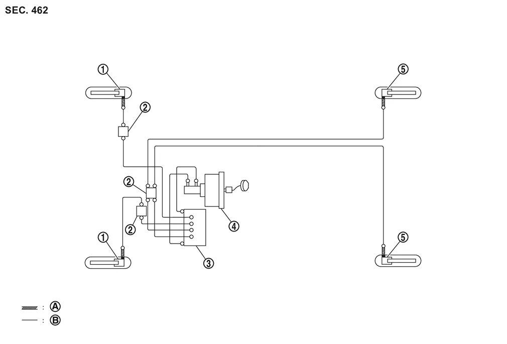
|
Front disc brake | |
Connector | |
ABS actuator and electric unit (control unit) |
|
Electrical brake control unit | |
Rear disc brake | ||
 |
Brake hose | |
Brake tube | ||
 |
: Flare nut | ||||
 |
: Union bolt | ||||
Removal and Installation
WARNING:
-
Jacking up or lift up the vehicle may the vehicle height to go down which cause a personal injury and/or damage to the air suspension component parts. Refer to Precaution for when Jacking and Lifting Up the vehicle with Electronic Air Suspension System.
REMOVAL
CAUTION:
-
Never spill or splash brake fluid on painted surfaces. Brake fluid may seriously damage paint. Wipe it off immediately and wash with water if it gets on a painted surface.
-
Never depress the brake pedal while removing the brake hose or brake tube. If this is not complied with, brake fluid may splash.
Remove tires. Refer to ROAD WHEEL TIRE : Removal & Installation.
Perform the advance preparation "(Air release) Accumulator pressure release" using CONSULT. Refer to Work Procedure.
Drain brake fluid. Refer to Draining.
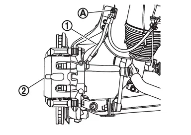
Loosen the flare nut with a flare nut wrench (A) and separate the brake tube from the brake hose .
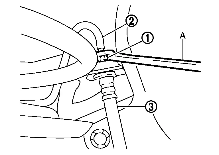
CAUTION:
-
Never scratch the flare nut and the brake tube.
-
Never bend sharply, twist or strongly pull out the brake hoses and tubes.
-
Cover open end of brake tubes and hoses when disconnecting to prevent entrance of dirt.
Remove the union bolt and copper washers .
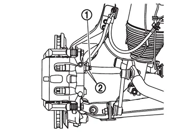
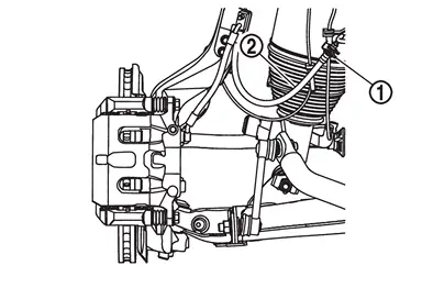
Remove the mounting nut , and remove brake hose from the brake caliper assembly .
Remove the lock plate and remove the brake hose .
INSTALLATION
CAUTION:
-
Never spill or splash brake fluid on painted surfaces. Brake fluid may seriously damage paint. Wipe it off immediately and wash with water if it gets on a painted surface.
-
Never depress the brake pedal while removing the brake hose or brake tube. If this is not complied with, brake fluid may splash.
-
Never allow foreign matter (e.g. dust) and oils other than brake fluid to enter the reservoir tank.
Assemble the union bolt and the copper washer to the brake hose .
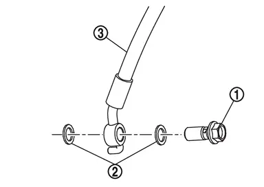
CAUTION:
Never reuse the copper washer.
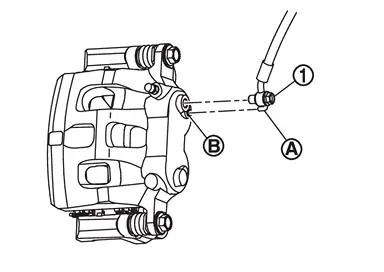
Install the brake hose L-pin by aligning it with the brake caliper assembly positioning hole , and tighten the union bolt to the specified torque. Refer to Exploded View.
Install the brake hose to the bracket , and install the mounting nut .
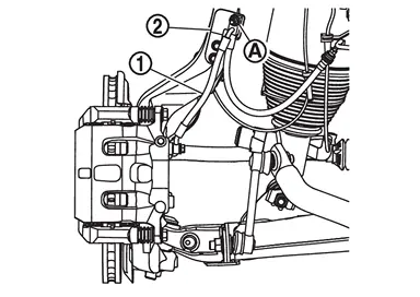
CAUTION:
Check that all brake hoses are not twisted and bent.
Install the brake tube to the brake hose , temporarily tighten the flare nut by hand until it does not rotate further, and fix the brake hose to the bracket with the lock plate .
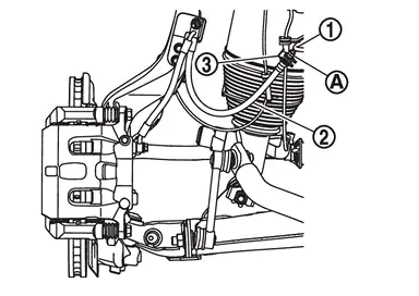
CAUTION:
Check that all brake hoses and brake tubes are not twisted and bent.
Tighten the flare nut to the specified torque with a flare nut torque wrench (A). Refer to Exploded View.
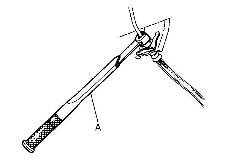
CAUTION:
Never scratch the flare nut and the brake tube.
Refill with new brake fluid and perform the air bleeding. Refer to Work Procedure.
CAUTION:
Never reuse drained brake fluid.
Install tires. Refer to ROAD WHEEL TIRE : Removal & Installation.
Perform inspection after installation. Refer to Inspection.
Inspection
INSPECTION AFTER INSTALLATION
Check the brake hoses and tubes for the following: no scratches; no twist and deformation; no interference with other components when steering the steering wheel; no looseness at connections.
CAUTION:
Clearance with brake hose and each parts being secured more than 10 mm (0.39 in) in unladen condition*.
*: Fuel, engine coolant and lubricant are quantity to specified. Spare tire, jack, hand tools and mats are brought out of vehicle.
Depress the brake pedal with a force of 785 N (80 kg, 176 lb) and hold down the pedal for approximately 5 seconds with the engine running. Check for any fluid leakage.
CAUTION:
Retighten the applicable connection to the specified torque and repair any abnormal (damaged, worn or deformed) part if any brake fluid leakage is present.
Other materials
Engine Coolant
Inspection
LEVEL
Check if the reservoir tank engine coolant level is within the “MIN� to “MAX� when the engine is cool.
: MAX
: MIN
Adjust the engine coolant level if necessary.
WARNING:
Never remove reservoir tank cap when engine is hot.
CAUTION:
Refill Genuine NISSAN Long Lif ...
Head up Display Screen Is Not Displayed in the Correct Position
Diagnosis Procedure
CHECK HEAD UP DISPLAY POSITION ADJUSTMENT SIGNAL
With CONSULT
Select "Data Monitor" mode of "Head Up Display� using CONSULT.
Check "Display up and down status" and "Display rotation status" indication as per the following condition.
Monitor item Condition Indication
Di ...
Action Test
Work Procedure
After repairing the malfunction symptom of ProPILOT Assist 2.1, perform an operation check of ProPILOT Assist 2.1 and check that ProPILOT Assist 2.1 operates normally.CAUTION:
Always drive safely when performing the action test.CHECK FOR ProPILOT ASSIST SWITCH
Start the engine.
Pr ...