Exploded View
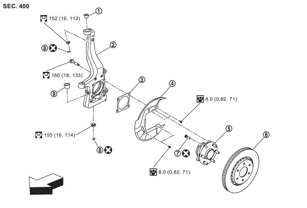
 |
Upper ball seat |  |
Steering knuckle |  |
Baffle |
 |
Splash guard |  |
Wheel hub and bearing assembly |  |
Disc rotor |
 |
Hub bolt |  |
Cotter pin |  |
Lower ball seat |
| : vehicle front | |||||
 |
: N·m (kg-m, in-lb) | ||||
 |
: N·m (kg-m, ft-lb) | ||||
 |
: Always replace after every disassembly. | ||||
Removal and Installation
WARNING:
-
Jacking up or lift up the vehicle may the vehicle height to go down which cause a personal injury and/or damage to the air suspension component parts. Refer to Precaution for when Jacking and Lifting Up the vehicle with Electronic Air Suspension System.
REMOVAL
Remove tires. Refer to ROAD WHEEL TIRE : Removal & Installation.
Remove brake hose bracket. Refer to Removal and Installation.
Remove brake caliper assembly. Hang brake caliper assembly in a place where it will not interfere with work. Refer to FRONT BRAKE CALIPER ASSEMBLY : Removal & Installation.
CAUTION:
Never depress brake pedal while brake caliper is removed.
Remove disc rotor.
CAUTION:
-
Put matching marks
 on the wheel hub assembly and the disc rotor before removing the disc rotor.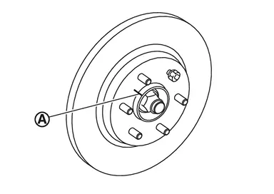
-
Never drop disc rotor.
Remove wheel sensor harness. Refer to Removal and Installation.
Remove steering outer socket. Refer to Removal and Installation.
Set suitable jack under lower link.
Remove shock absorber mounting bolt from lower link. Refer to Removal and Installation.
Remove wheel hub and bearing assembly, and then remove splash guard and baffle.
Separate upper link from steering knuckle, using the ball joint remover (commercial service tool), and remove upper link.
CAUTION:
-
Temporarily tighten the nut to prevent damage to threads and to prevent the ball joint remover from suddenly coming off.
-
Never damage ball joint boot.
Remove lower link from steering knuckle.
CAUTION:
Never damage ball joint boot.
Remove steering knuckle.
Remove hub bolts from wheel hub assembly, using the ball joint remover (commercial service tool) (A).
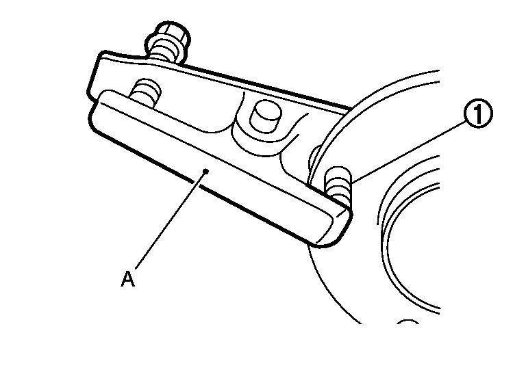
CAUTION:
-
Only remove the hub bolt when it is necessary to do so.
-
Tap the hub bolt with a hammer or other means, without exerting any impact on the wheel hub assembly.
-
Remove the hub bolt perpendicularly from the wheel hub assembly.
Perform inspection after removal. Refer to Inspection.
INSTALLATION
Note the following, and install in the reverse order of the removal.
Hub Bolts
Place a suitable washer as shown in the figure to install the hub bolts by using the tightening force of the nut  .
.
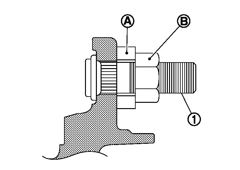
CAUTION:
-
Check that there is no clearance between wheel hub, and hub bolt.
-
Never reuse hub bolt.
Disc rotor
CAUTION:
-
Align the matching marks
made during removal when reusing the disc rotor. -
Never drop disc rotor.
Inspection
INSPECTION AFTER REMOVAL
Check the following items, and replace the part if necessary.
Ball Joint Inspection
Check boots of upper link, lower link and steering outer socket ball joint for breakage, axial play, and swing torque:
-
Upper link: Refer to Inspection.
-
Lower link: Refer to Inspection.
-
Steering outer socket ball joint: Refer to Inspection.
INSPECTION AFTER INSTALLATION
Check runout of disc rotor, when replaced the disc rotor. Refer to Inspection and Adjustment.
Check wheel sensor harness for proper connection. Refer to Exploded View.
Check the wheel alignment. Refer to Inspection.
Adjust neutral position of steering angle sensor. Refer to Work Procedure.
Other materials
Steering Angle Sensor
Removal and Installation
REMOVALRemove spiral cable assembly. Refer to Removal and Installation.
Remove steering angle sensor from spiral cable.INSTALLATIONNote the following, and install in the reverse order of removal.
When replacing the angle sensor , if the lock pin is installed, remove the lo ...
Seat Tools and Preparation
Special Service Tools
The actual shapes of TechMate tools may differ from those of special service tools illustrated here.
Tool number
(TechMate No.)
Tool name Description
(NI-39570)
Chassis ear
Locates the noise
(NI-50397)
Squeak and Rattle Kit
Repairs the cause of noise
Commerci ...
Back Door Weather-Strip
Removal and Installation
REMOVALPull up and remove engagement with body from the seam of back door weather-strip.CAUTION:
Never pull strongly on back door weather-strip.
When removing back door weather-strip, pull it away from the vehicle by holding back door weather-strip by the base part , and ...