Work Procedure
Description
Calibration must be performed after replacing or removing/installing the following parts..
-
Head Up Display unit
-
Windshield glass
-
Steering member
Diagnosis Procedure
 NOTE:
NOTE:
-
Place the vehicle on level ground.
-
Keep the space when calibration. (vehicle front area)
-
Wide: 2.0 m (6.56 ft)
-
Height: 2.0 m (6.56 ft)
-
Length: 2.0 m (6.56 ft)
-
TARGET PREPARATION
Prepare the distortion calibration jig according to the following procedure and the figure.
-
Prepare target sheet according to the figure.
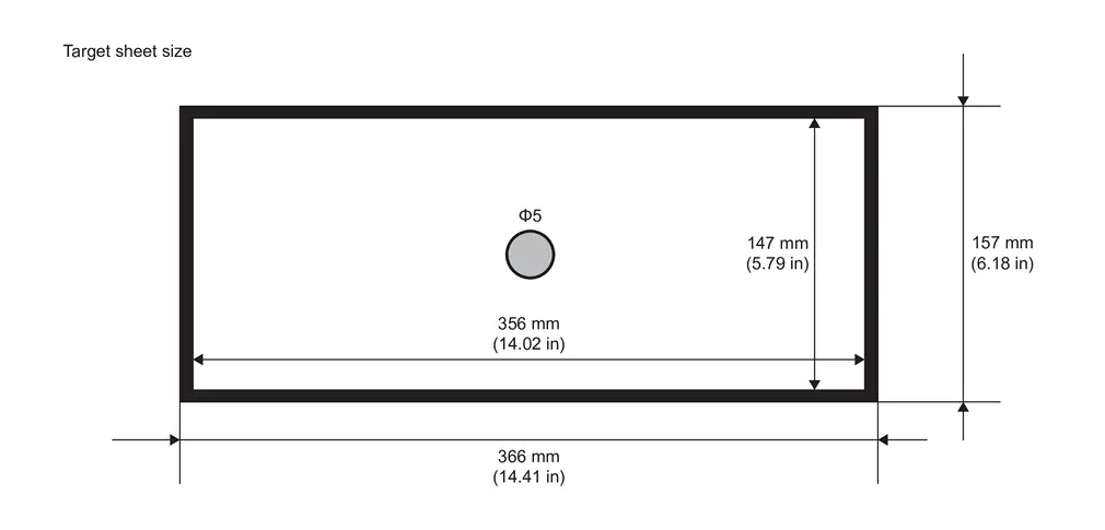
-
Paste the created target sheet onto the board according to the figure.
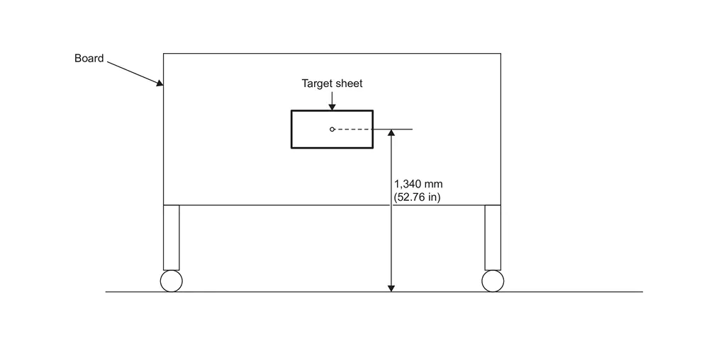
>>
GO TO 2.
TARGET SETTING
-
Mark points “A”, “B”, “C” and “D” at the center position of each wheels.
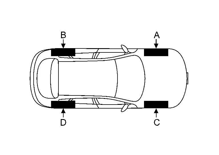
-
Draw line "LH (RH)" passing through points "A (C)" and "B (D)" on the left (right) side of vehicle.
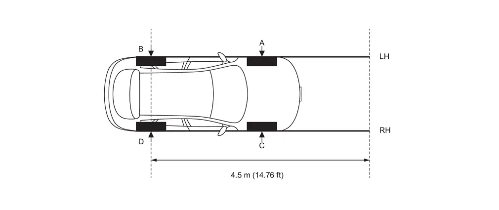 NOTE:
NOTE:
Approximately 4.5 m (14.76 ft) or more from the point "B (D)".
-
Mark point "E (F)" on the line "LH (RH)" at the positions 1,530 mm (60.24 in) from point "A (C)". And then draw line "FW" passing through the points "E" and "F".
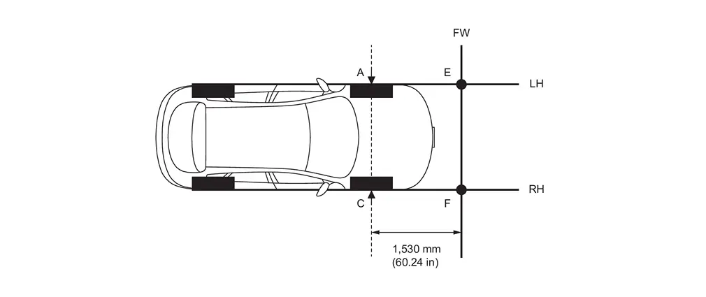
-
Place the target board on the line "FW" so that the center of the target comes to 510 mm (20.08 in) from mark point "E".
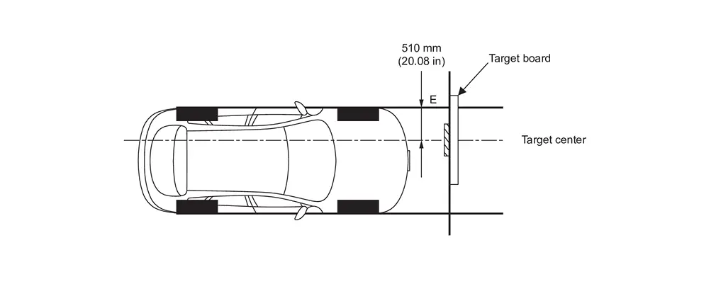
>>
GO TO 3.
DRIVER'S SEAT POSITION ADJUSTMENT
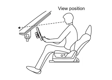
Adjust the driver's seat and steering wheel to the position shown in the figure.
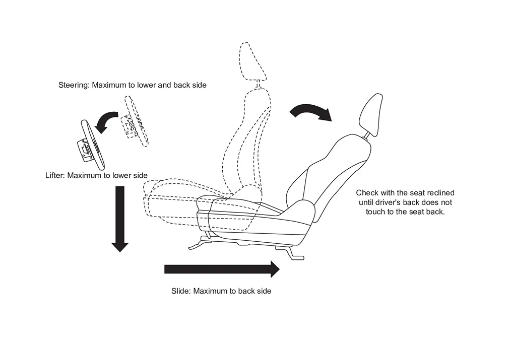
>>
GO TO 4.
RESET OPERATION
-
Turn ignition switch ON.
-
Touch "Reset" on the Head Up Display setting screen of the combination meter and reset the setting. Refer to Switch Name and Function.
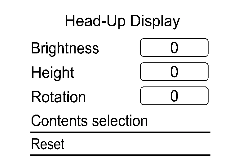
>>
GO TO 5.
TARGET CENTER POSITION ADJUSTMENT
With CONSULT
-
Select "Distortion calibration" of "Work Support" on "Head Up Display” using CONSULT.
-
Confirm from the driver's seat whether the center position of the displayed guideline is coincident with the center position of the target sheet.
NOTE:
If there is a gap between the center of the guideline and the target sheet,do not change the vehicle position, and match the center point by moving the target seat and target seat up and down, back and forth with setting the design standard dimension as a basic point.
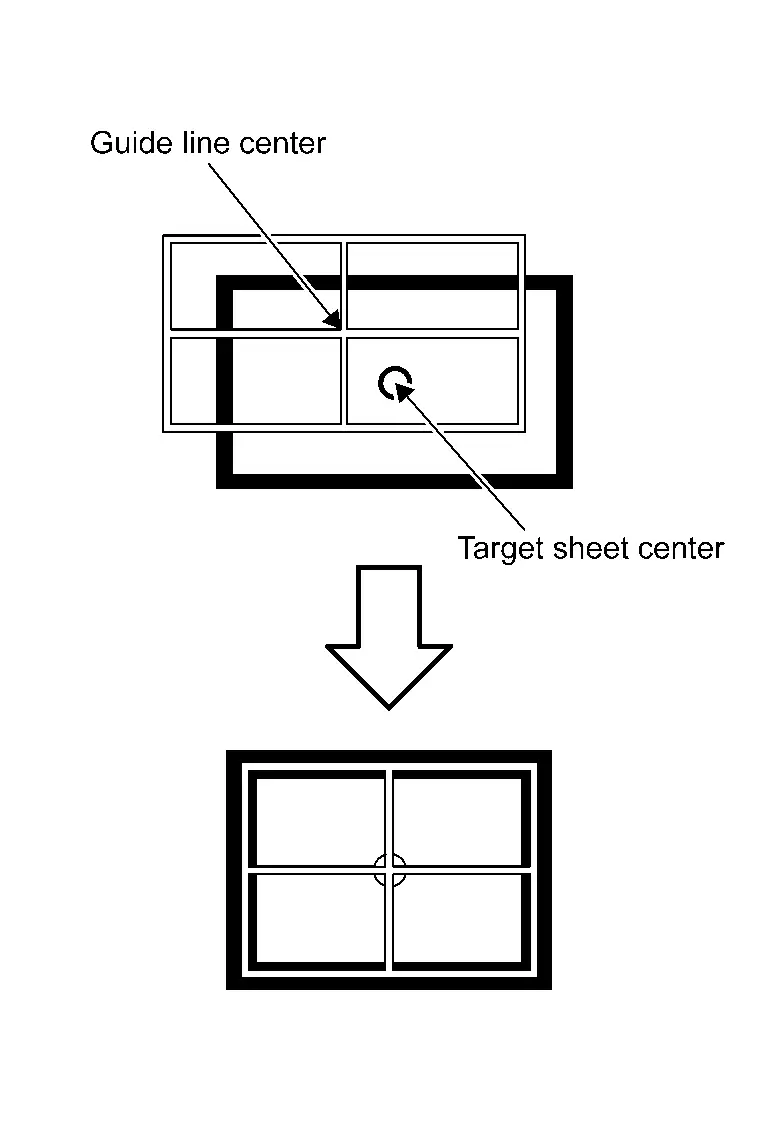
>>
GO TO 6.
PERFORM DISTORTION CALIBRATION
With CONSULT
-
Visually check for the distortion of the guideline from the standard HUD design view-point (Refer to 5-2).

-
If the guideline display is distorted, touch "+" or "-" of the item corresponding to the distortion type to be corrected according to following table, and calibrate to match the target sheet.
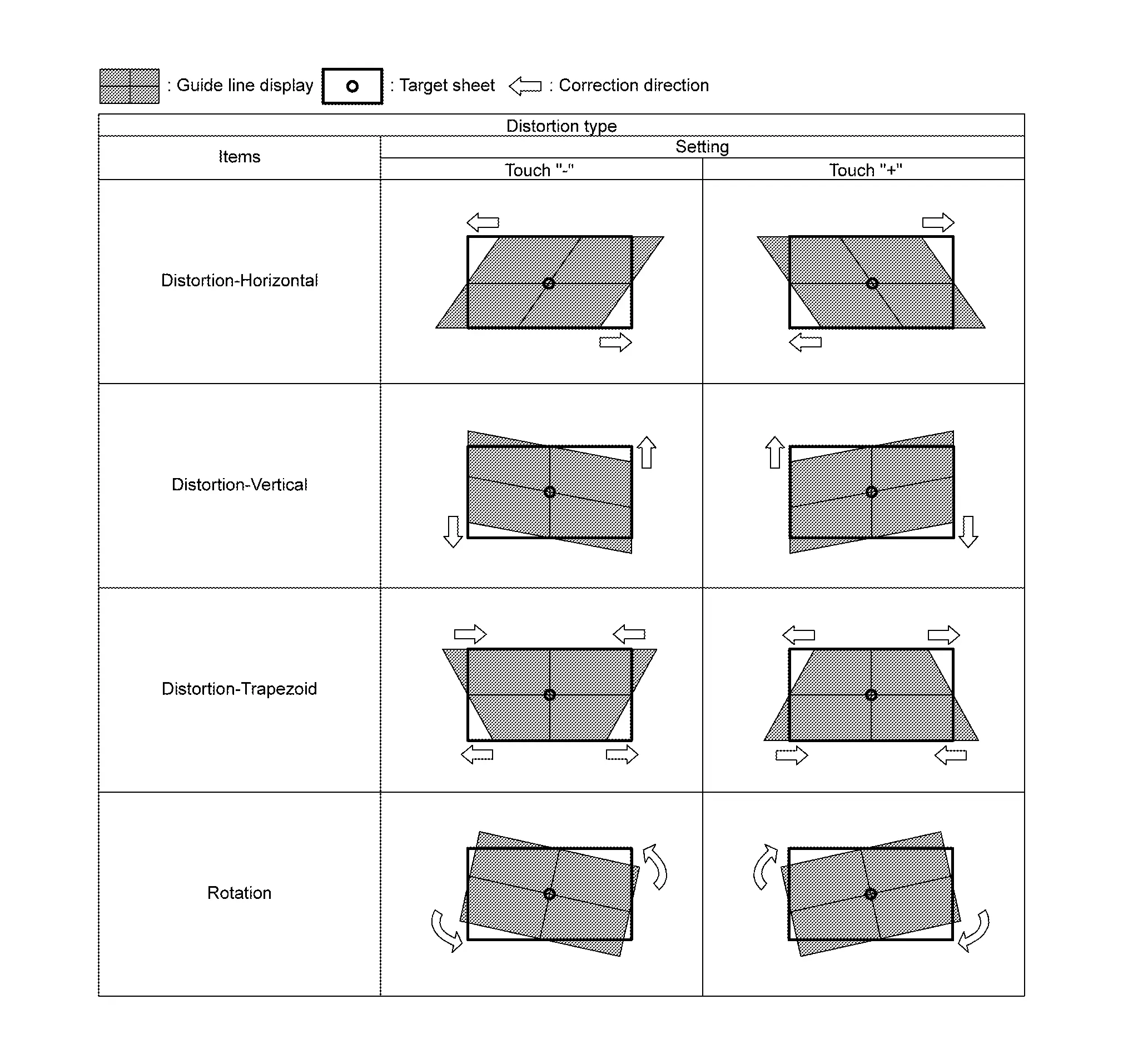
-
Touch "Save" and save the setting when calibration is completed.
NOTE:
Touch "Reset" to cancel the change.
>>
WORK END
Other materials
Rear Bumper
Exploded View
Rear bumper side bracket LH
Rear bumper bracket RH
Rear bumper bracket LH
Hands free sensor bracket
(with hands free sensor models)
Double-sided tape
[t: 1.2 mm (0.047 in)]
(with hands free sensor models)
Rear bumper fascia
Rear bumper molding LH
Rear bumper fi ...
Combination Meter
Removal and Installation
CAUTION:
When replacing the combination meter, always replace it with a new one. The functions controlled by the combination meter does not operate properly in case of reuse of the combination meter from another vehicle.
Be sure to perform the configuration when replacin ...
Vin Registration
Work Procedure
VIN Registration is an operation to register the VIN in ADAS control unit.CHECK VIN
Check VIN of vehicle and note it. For VIN stamped position, refer to Information About Identification or Model Code .
>>
GO TO 2 .
PERFORM VIN REGISTRATION
With CONSULT
Ignition switch ON.
...