Exploded View
Bank 1 side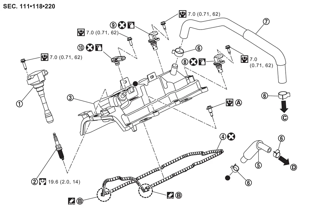
 |
Ignition coil |  |
Spark plug |  |
Rocker cover |
 |
Rocker cover gasket |  |
Blow-by hose 1 (bank 1) |  |
Clamp |
 |
Blow-by hose 2 (bank 1) |  |
Intake camshaft position sensor |  |
Exhaust camshaft position sensor |
 |
Crankcase pressure sensor | ||||
 |
Comply with the installation procedure when tightening. Refer to Removal and Installation. |  |
Camshaft bracket side |  |
To rocker cover (bank 2). |
 |
To intake manifold. Refer to Exploded View. | ||||
 |
: N·m (kg-m, ft-lb) | ||||
 |
: N·m (kg-m, in-lb) | ||||
 |
: Always replace after every disassembly. | ||||
 |
: Should be lubricated with oil. | ||||
 |
: Sealing point | ||||
 |
: Indicates that the parts is connected at points with same symbols in actual vehicle. | ||||
Bank 2 side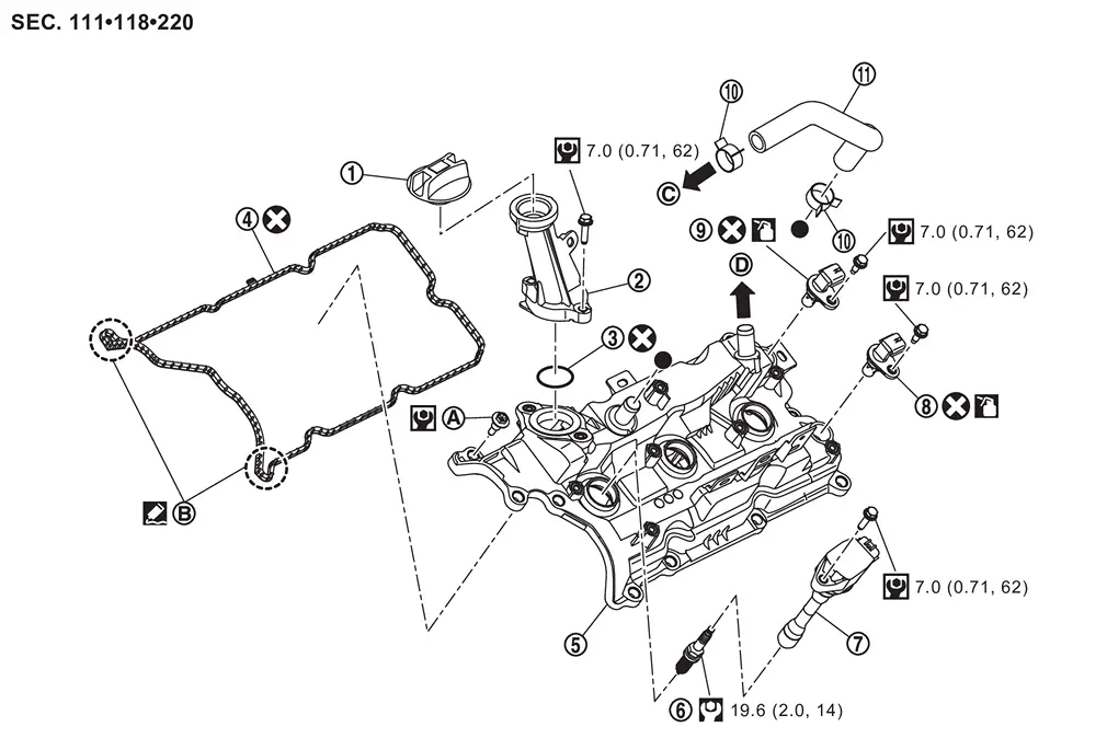
|
Oil filler cap | |
Oil filler tube | |
O-ring |
|
Rocker cover gasket | |
Rocker cover | |
Spark plug |
|
Ignition coil | |
Intake camshaft position sensor | |
Exhaust camshaft position sensor |
|
Clamp |  |
Blow-by hose (bank 2) | ||
|
Comply with the installation procedure when tightening. Refer to Removal and Installation. | |
Camshaft bracket side | |
To air duct. Refer to Exploded View. |
|
To rocker cover (bank 1). | ||||
|
: N·m (kg-m, ft-lb) | ||||
|
: N·m (kg-m, in-lb) | ||||
|
: Always replace after every disassembly. | ||||
|
: Should be lubricated with oil. | ||||
|
: Sealing point | ||||
|
: Indicates that the parts is connected at points with same symbols in actual vehicle. | ||||
Removal and Installation
WARNING:
-
Jacking up or lift up the vehicle may the vehicle height to go down which cause a personal injury and/or damage to the air suspension component parts. Refer to Precaution for when Jacking and Lifting Up the vehicle with Electronic Air Suspension System.
REMOVAL
Ignition coil
 NOTE:
NOTE:
No. 2-No. 5 can be removed using only the ignition coil.
Remove engine cover. Refer to Removal and Installation.
Remove mounting bolt from air inlet tube 1  . (No. 1 and No. 6 cylinder)
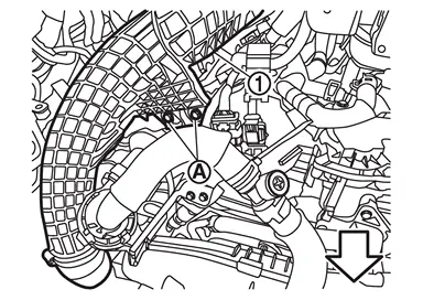
| : vehicle front |
Remove mounting bolt from air inlet tube 1 . (No. 1 and No. 6 cylinder)
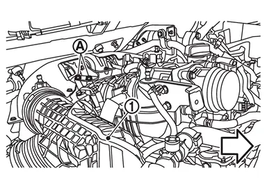
| : vehicle front |
Remove mounting bolt from air inlet tube 1 . (No. 1 and No. 6 cylinder)
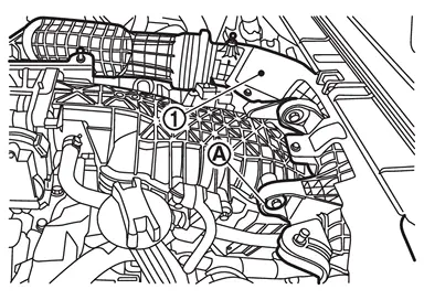
Remove air inlet tube 1 from turbocharger (bank 1 side). (No. 1 and No. 6 cylinder)
Refer to Removal & Installation.
Move air inlet tube 1 to a position where it is easier to work. (No. 1 and No. 6 cylinder)
Remove ignition coil.
CAUTION:
Never shock ignition coil.
Rocker cover
Remove the following parts:
-
Engine cover: Refer to Removal and Installation.
-
Air cleaner assembly: Refer to Removal and Installation.
-
Air inlet tube: Refer to Removal & Installation.
-
Intake manifold: Refer to Removal and Installation.
Remove bank 1 by following the steps below.Remove ignition coil.
CAUTION:
Never shock ignition coil.
Remove blow-by hose 1 (bank 1) and blow-by hose 2 (bank 1) .
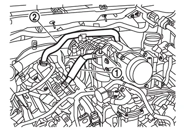
.
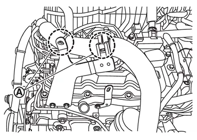
.
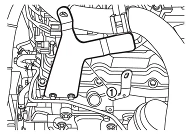
Remove bank 2 by following the steps below.Remove crankcase ventilation valve and resonator as a set. Remove blow-by hose (bank 2) .
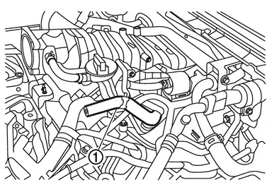
CAUTION:
Never shock ignition coil.
Disconnect the cylinder block heater harness connector from cylinder block. (For CANADA) Disconnect the high pressure fuel pump harness connector. Refer to Removal & Installation. Remove high pressure fuel pump insulator. Refer to Removal & Installation. Disconnect the electric throttle control actuator harness connector. Refer to Exploded View. Disconnect the recirculation valve harness connector. Refer to Exploded View. Disconnect the electric intake valve timing control actuator (bank 2) harness connector. Refer to Exploded View. Disconnect the camshaft position sensor harness connector. (intake and exhaust)Loosen mounting bolts in the order from 10 to 1 (bank 1 ), and for (bank 2 ), from 11 to 1 as shown in the figure.
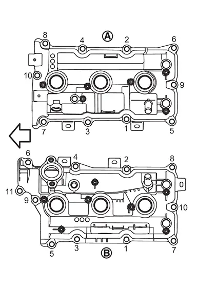
| : Engine front |
Remove rocker cover gasket from rocker cover.
INSTALLATION
NOTE:
If an intake camshaft position sensor or exhaust camshaft position sensor are replaced, carry out the teach of “Electric IVT Control Actuator Position Learning”. Refer to Work Procedure.
Apply liquid gasket to the positions shown.
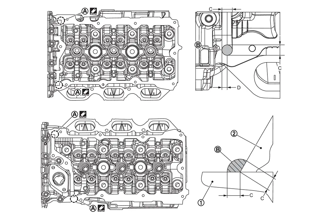
|
: Cylinder head |
|
: Camshaft bracket (No. 1) |
| C | : 10 mm (0.39 in) |
| D | : 4 mm (0.16 in) (Application position of liquid gasket from the end surface of the camshaft bracket) |
-
Use Genuine RTV Silicone Sealant or an equivalent. Refer to Recommended Chemical Products and Sealants.
Install the rocker cover using the following steps:
Bank 1 side
Install guide pin in the shown figure 9.
| : Engine front | |
|
: Bank 1 side |
|
: Bank 2 side |
NOTE:
Guide pin are included with the replacement part.
Temporarily tighten the mounting bolts in the order shown in figure 1 to 8.
| : 1.96 N·m (0.2 kg-m, 17 in-lb) |
Remove the guide pin.
Temporarily tighten the mounting bolts in the order shown in figure 9 to 10.
| : 1.96 N·m (0.2 kg-m, 17 in-lb) |
Tighten to the specified torque in the order 1 to 10 shown in the figure.
| : 8.33 N m (0.85 kg-m, 74 in-lb) |
Bank 2 side
Install guide pin in the shown figure 10.
| : Engine front | |
|
: Bank 1 side |
|
: Bank 2 side |
NOTE:
Guide pin are included with the replacement part.
Temporarily tighten the mounting bolts in the order shown in figure 1 to 9.
| : 1.96 N·m (0.2 kg-m, 17 in-lb) |
Remove the guide pin.
Temporarily tighten the mounting bolts in the order shown in figure 10 to 11.
| : 1.96 N·m (0.2 kg-m, 17 in-lb) |
Tighten to the specified torque in the order 1 to 11 shown in the figure.
| : 8.33 N m (0.85 kg-m, 74 in-lb) |
Other materials
Basic information
Touch screen display
WARNING
Failure to follow proper Nissan Armada RearView Monitor usage instructions
may result in serious injury or fatal accidents.
The Nissan Armada RearView Monitor is an assistance feature and must
not replace proper driving practices.
Always visual ...
Engine Lubrication System Service Data and Specifications
ENGINE OIL
ENGINE OIL CAPACITY (APPROXIMATE)Unit: (US qt, lmp qt) Drain and refill
With oil filter change
6.0 (6-3/8, 5-2/8)
Without oil filter change
5.6 (5-7/8, 4-7/8)
Dry engine (Overhaul)
7.2 (7-5/8, 6-3/8)
Engine Oil Pressure
Unit: kPa (kg/cm2, psi)
Engine speed
Approximate ...
Parking, License Plate, Side Marker and Tail Lamps Are Not Turned on
Description
The parking, license plate, side marker and tail lamps are not turned ON in any condition.
Diagnosis Procedure
COMBINATION SWITCH INSPECTION
Check combination switch. Refer to Symptom Table.
Is the inspection result normal?
YES>>
GO TO 2.
NO>>
Repair or replace the malfun ...