
Nissan Armada 2025-2026 Service and Repair Manual: Inspection
INSPECTION AFTER DISASSEMBLY
Cylinder Head Bolts Outer Diameter
Cylinder head bolts are tightened by plastic zone tightening method. Whenever the size difference between
 and
and  exceeds the limit, replace them with new one.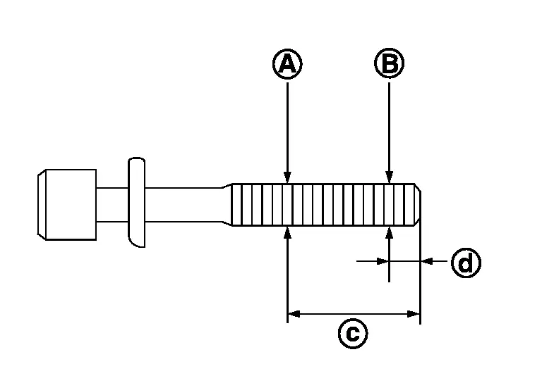

: 50.5 mm (1.988 in) 
: 11 mm (0.43 in) Limit [ - ] : 0.16 mm (0.0063 in) If reduction of outer diameter appears in a position other than
, use it as point.
Cylinder Head Distortion
 NOTE:
NOTE:
When performing this inspection, cylinder block distortion should be also checked. Refer to Inspection.
Using a scraper, wipe off oil, scale, gasket, sealant and carbon deposits from surface of cylinder head.
CAUTION:
Never allow gasket fragments to enter engine oil or engine coolant passages.
At each of several locations on bottom surface of cylinder head, measure the distortion in six directions , ,  ,
,  ,
,  , and
, and  ).
).
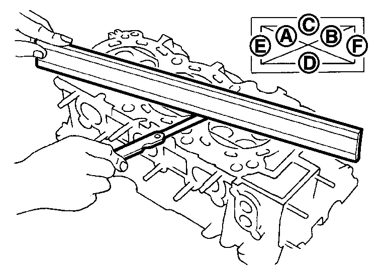
| Limit | : Refer to CylinderHead. |
If it exceeds the limit, replace cylinder head.
Valve Dimensions
Check the dimensions of each valve. For the dimensions, Refer to CylinderHead.
If dimensions are out of the standard, replace valve and check valve seat contact. Refer to “VALVE SEAT CONTACT�
Valve Guide Clearance
Valve Stem Diameter
Measure the diameter of valve stem with micrometer (A).
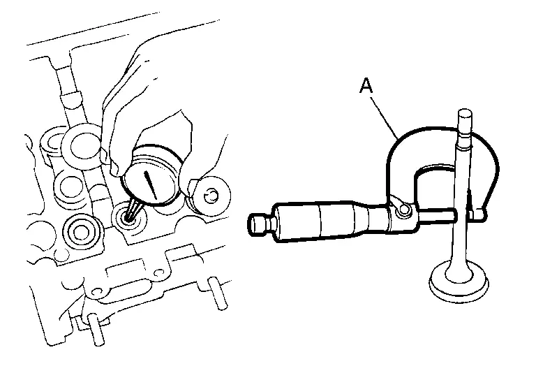
Standard : Refer to CylinderHead.
Valve Guide Inner Diameter
Measure the inner diameter of valve guide with bore gauge.
Standard : Refer to CylinderHead.
Valve Guide Clearance
(Valve guide clearance) = (Valve guide inner diameter) – (Valve stem diameter)
Standard : Refer to CylinderHead.
If the calculated value exceeds the limit, replace valve and/or valve guide. When valve guide must be replaced, Refer to Removal & Installation.
Valve Seat Contact
After confirming that the dimensions of valve guides and valves are within the specifications, perform this procedure.
Apply prussian blue (or white lead) onto contacting surface of valve seat to check the condition of the valve contact on the surface.
Check if the contact area band is continuous all around the circumference.
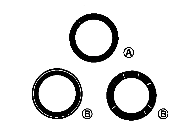
: OK : NG If not, grind to adjust valve fitting and check again. If the contacting surface still has “NG� conditions even after the recheck, replace valve seat. Refer to Exploded View.
Valve Spring Squareness
Set a try square (A) along the side of valve spring and rotate spring. Measure the maximum clearance
between the top of spring and try square.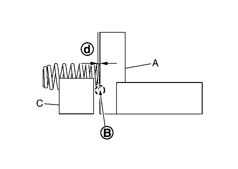
: Contact C : V-block Limit : Refer to CylinderHead. If it exceeds the limit, replace valve spring.
Valve Spring Dimensions and Valve Spring Pressure Load
Check the valve spring pressure at specified spring height.
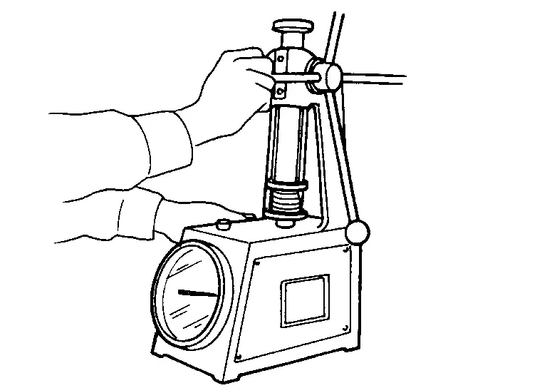
Standard :Refer to CylinderHead. If the installation load or load with valve open is out of the standard, replace valve spring.
INSPECTION AFTER INSTALLATION
Inspection for Leakage
The following are procedures for checking fluid leakage, lubricant leakage.
Before starting engine, check oil/fluid levels including engine coolant and engine oil. If any are less than the required quantity, fill them to the specified level. Refer to Fluids and Lubricants.
Follow the procedure below to check for fuel leakage.
Turn ignition switch to the “ON� position (with engine stopped). With fuel pressure applied to fuel piping, check for fuel leakage at connection points.
Run engine to check for unusual noise and vibration.
NOTE:If hydraulic pressure inside chain tensioner drops after removal/installation, slack in guide may generate a pounding noise during and just after the engine start. However, this does not indicate a malfunction. The noise will stop after hydraulic pressure rises.
Warm up engine thoroughly to check that there is no leakage of fuel, or any oil/fluids including engine oil and engine coolant.
Bleed air from lines and hoses of applicable lines, such as in cooling system.
Summary of the inspection items: Items Before starting engine Engine running After engine stopped Engine coolant Level Leakage Level Engine oil Level Leakage Level Transmission / transaxle fluid AT & CVT Models Leakage Level / Leakage Leakage MT Models Level / Leakage Leakage Level / Leakage Other oils and fluids* Level Leakage Level Fuel Leakage Leakage Leakage Exhaust gases — Leakage — *: Power steering fluid, brake fluid, etc.
 Removal & Installation
WARNING:
DISASSEMBLY
Remove the following parts:
Intake manifold: Refer to Removal and Installation.
Spark plug: Refer to Removal & Installation.
Rocker cover: Refer to Removal and Installation.
...
 Front Oil Seal
...
Other materials:
Removal and Installation
CAUTION:
Never damage the body panel.
REMOVAL
CAUTION:
Remove luggage side lower finisher. Refer to Removal and Installation.
Apply protective tape (A) on rear pillar finisher to protect it from damage.
Disengage seat belt finisher fixing pawls using a remover tool (A).
: Pawl
Apply protectiv ...
Exploded View
Bracket A/T assembly Bracket Transfer assembly Bracket : N·m (kg-m, ft-lb) ...
Pantograph Jack
WARNING:
Jacking up or lifting up the vehicle may the vehicle height to go down which cause a personal injury and/or damage to the air suspension component parts. Refer to Precaution for when Jacking and Lifting Up the Vehicle with Electronic Air Suspension System (With electronic air suspension).
W ...

0.006