
Nissan Armada 2025-2026 Service and Repair Manual: Removal & Installation
WARNING:
DISASSEMBLY
Remove the following parts:
Intake manifold: Refer to Removal and Installation.
Spark plug: Refer to Removal & Installation.
Rocker cover: Refer to Removal and Installation.
Intake manifold: Refer to Removal and Installation.
Fuel tube and fuel injector assembly: Refer to Removal and Installation.
Timing chain: Refer to Removal and Installation.
Camshaft: Refer to Removal & Installation.
Turbocharger: Refer to Removal & Installation.
Remove cylinder head bolts in the order from 8 to 1 (bank 1  ), and for (bank 2
  ), from 10 to 1 as shown in the figure with cylinder head bolt wrench (commercial service tool) and power tool to remove cylinder heads (bank 1 and bank 2).
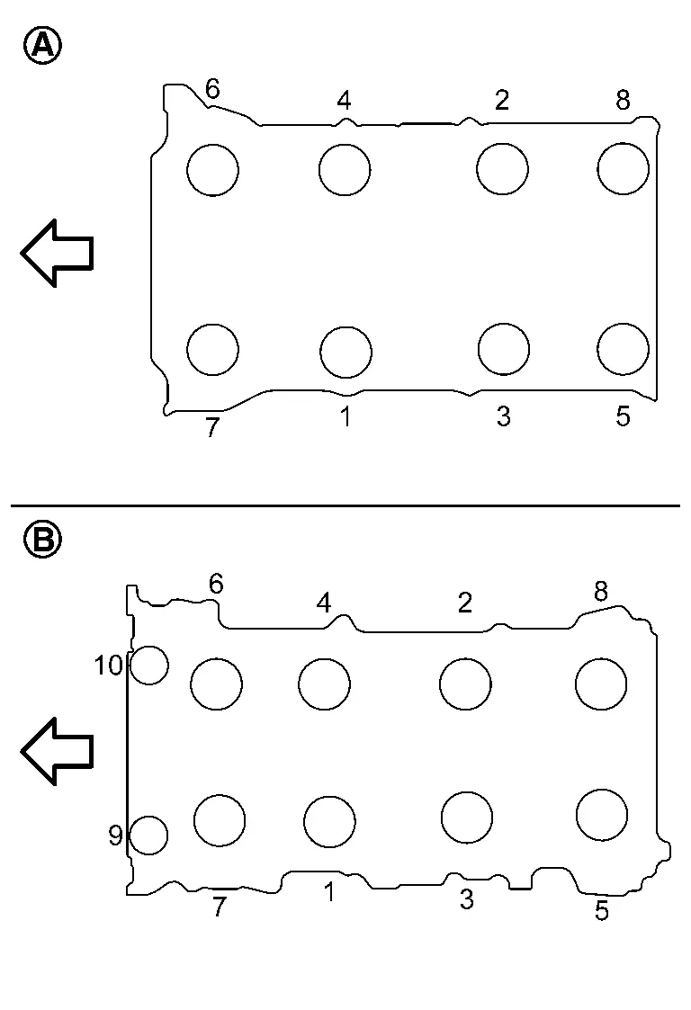
 | : Engine front |
Remove cylinder head gaskets.
Remove valve lifter.
Identify installation positions, and store them without mixing them up.
Remove valve collet.
Compress valve spring with the valve spring compressor [SST: KV10116200 (NI-26336-A)] (A), the attachment [SST: KV10115900 (NI-26336-20)] (C) and the adapter [SST: KV10109220 ( — )] (B). Remove valve collet with a magnet hand.
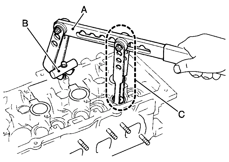
CAUTION:
Be careful not to damage valve lifter holes.
Fit the attachment [SST: KV10115900 (NI-26336-20)] in the center of valve spring retainer to press it.
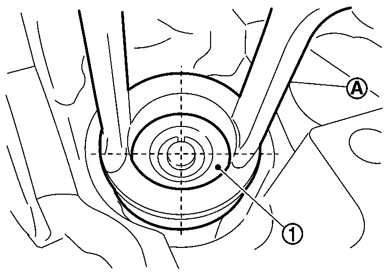

: Valve spring retainer : Attachment
Remove valve spring retainer, valve spring and valve spring seat.
Push valve stem to combustion chamber side, and remove valve.
Identify installation positions, and store them without mixing them up.
Remove valve oil seal using the valve oil seal puller [SST: KV10107902 (NI-38959)] (A).
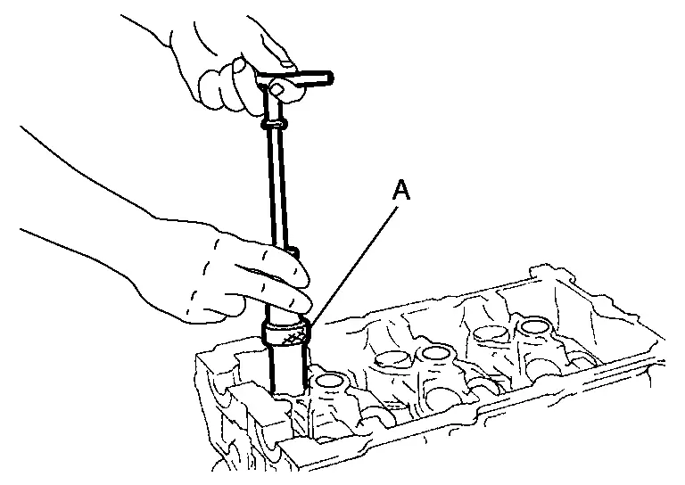
Remove valve seat, if valve seat must be replaced.
Bore out old seat until it collapses. Boring should not continue beyond the bottom face of the seat recess in cylinder head. Set the machine depth stop to ensure this.Refer to CylinderHead.
CAUTION:
Prevent to scratch cylinder head by excessive boring.
Remove valve guide, if valve guide must be replaced.To remove valve guide, heat cylinder head to 110 to 130°C (230 to 266°F) by soaking in heated oil .
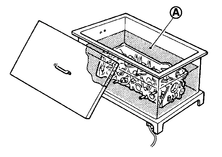
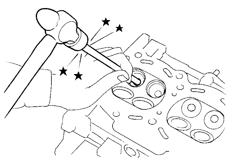
WARNING:
Cylinder head contains heat. When working, wear protective equipment to avoid getting burned.
ASSEMBLY
If valve guide is removed in step 10 (DISASSEMBLY), install it.
Replace with oversized [0.2 mm (0.008 in)] valve guide.
Using the valve guide reamer (commercial service tool) (A), ream cylinder head valve guide hole.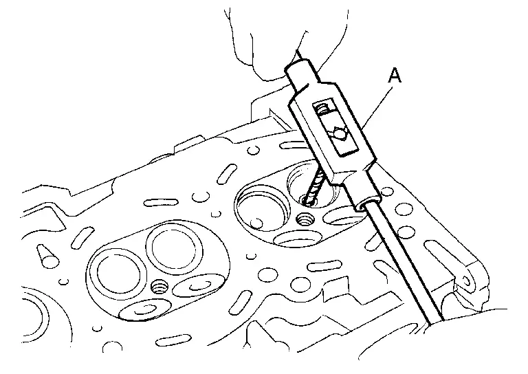
| Oversize (service) [0.2 mm (0.008 in)]: | ||
| : Refer to CylinderHead. | ||
.
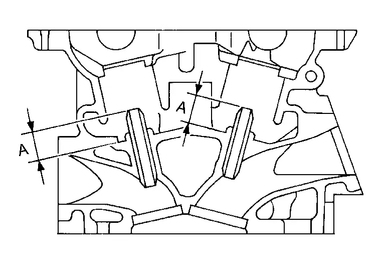
| Projection (A) | ||
| : Refer to CylinderHead. | ||
WARNING:
Using the valve guide reamer (commercial service tool) (A), apply reamer finish to valve guide.
| Standard | : Refer to CylinderHead. |
If valve seat is removed in step 9 (DISASSEMBLY), install it.
Replace with oversize [0.5 mm (0.020 in)] valve seat.
Ream cylinder head recess diameter for service valve seat.
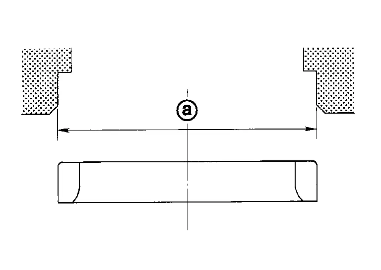
| Oversize (service) [0.5 mm (0.020 in)]: | |
| : Refer to CylinderHead. | |
Be sure to ream in circles concentric to valve guide center. This will enable valve to fit correctly.
.
WARNING:
CAUTION:
Avoid directly touching cold valve seats.
Using the valve seat cutter set (commercial service tool) or valve seat grinder, finish seat to the specified dimensions. Refer to CylinderHead.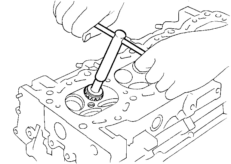
CAUTION:
When using the valve seat cutter, firmly grip cutter handle with both hands. Then, press on the contacting surface all around the circumference to cut in a single drive. Improper pressure on cutter or cutting many different times may result in staged valve seat.
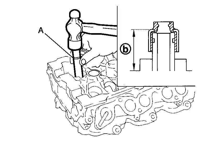
Using compound, grind to adjust valve fitting. Check again for normal contact. Refer to “VALVE SEAT CONTACT�.Install new valve oil seals as follows.Apply new engine oil on new valve oil seal joint and seal lip. Using the valve oil seal drift [SST: KV10115600 (NI-38958)] (A), press fit valve seal to height  shown in figure.
 NOTE:
NOTE:
Dimension: Height measured before valve spring seat installation
| Height (INT) | : 14.3 - 14.9 mm (0.563 - 0.587 in) |
| Height (EXH) | : 15.75 - 16.35 mm (0.6201 - 0.6437 in) |
Install valve spring seat.
Install valve.
NOTE:
Larger diameter valves are for intake side.
Install new cylinder head gaskets.
Turn crankshaft until No. 1 piston is set at TDC.
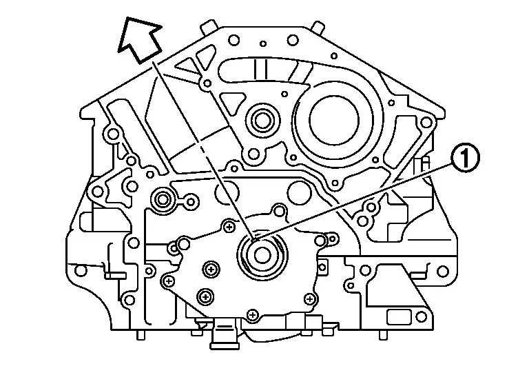
| : Crankshaft key |
| : Bank 1 side |
Crankshaft key should line up with the cylinder center line (bank 1) as shown in the figure.
Install cylinder head, and tighten cylinder head bolts in numerical order as shown in figure as follows:
| : Bank 1 |
| : Bank 2 |
| : Engine front |
Use the cylinder head bolt wrench [special service tool:  ST10120000  (NI-24239-01)] and power tool.
CAUTION:
If cylinder head bolts are re-used, check their outer diameters before installation. Refer to Inspection.
Before installing cylinder head, inspect cylinder head distortion. Refer to Inspection.
 : 40 N·m (4.1 kg-m, 30 ft-lb) : 40 N·m (4.1 kg-m, 30 ft-lb) |
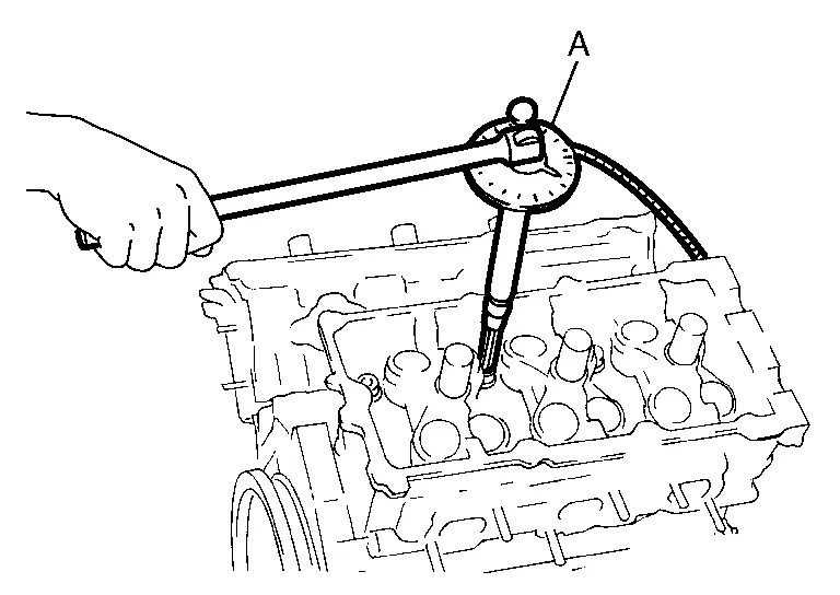
CAUTION:
Check the tightening angle by using the angle wrench [SST: KV10112100 (BT-8653-A)] (A). Avoid judgment by visual inspection without.
Check tightening angle indicated on the angle wrench indicator plate.
| : 28.0 N·m (2.9 kg-m, 21 ft-lb) |
Install valve spring (with valve spring seat).
Install large diameter side of valve spring (valve spring seat side) to cylinder head side
.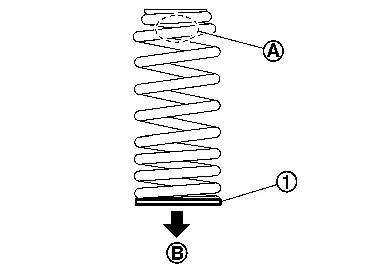
: Valve spring seat Confirm identification color
of valve spring.Intake : Pink Exhaust : Yellow
Install valve spring retainer.
Install valve collet.
Compress valve spring with the valve spring compressor [SST: KV10116200 (NI-26336-A)] (A), the attachment [SST: KV10115900 (NI-26336-20)] (C) and the adapter [SST: KV10109220 ( — )] (B). Install valve collet with a magnet hand.
CAUTION:
Be careful not to damage valve lifter holes.
Fit the attachment [SST: KV10115900 (NI-26336-20)] in the center of valve spring retainer to press it.
: Valve spring retainer : Attachment
Tap valve stem edge lightly with plastic hammer after installation to check its installed condition.
Install valve lifter.
Install it in the original position.
Install spark plug tube.
Press-fit spark plug tube as follows:
Use high strength thread locking sealant or equivalent.
Using drift, press-fit spark plug tube so that its height (A) is as specified in the figure.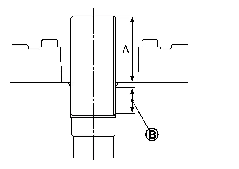
| : High strength thread locking sealant application area |
| Standard press-fit height: | |
| : 37.7 - 38.7 mm (1.484 - 1.524 in) | |
CAUTION:
When press-fitting, take care not to deform spark plug tube.
After press-fitting, wipe off liquid gasket protruding onto cylinder-head upper face.
Install spark plug. Refer to Removal & Installation.
Install in the reverse order of removal after this step.
 Exploded View
Valve lifter (EXH) Valve collet (EXH) Valve spring retainer (EXH) Valve oil seal (EXH) Valve spring (EXH) Valve spring seat (EXH) Valve guide (EXH) Spark plug tube Valve lifter (INT) Valve ...
 Inspection
INSPECTION AFTER DISASSEMBLY
Cylinder Head Bolts Outer Diameter
Cylinder head bolts are tightened by plastic zone tightening method. Whenever the size difference between and exceeds the limit, repla ...
Other materials:
Removal and Installation
CAUTION:
Never damage the body panel.
REMOVAL
CAUTION:
Remove luggage rear plate. Refer to Removal and Installation.
Release luggage side lower finisher portion of back door weather-strip. Refer to Removal and Installation.
Set second seat to walk-in position.
Remove third seat. Refer to Removal and ...
Diagnosis Procedure
A malfunction of brake pedal feel (height or others) is detected when the brake pedal is depressed.
CHECK AXLE
Check that there is no significant looseness of axle.
Front axle
2WD models: Refer to Inspection.
4WD models: Refer to Inspection.
Rear axle: Refer to Inspection.
Is the inspection result ...
How to enable/disable the LDW system
Vehicle information display
Steering-wheel-mounted controls (right side)
Basic information
To activate or deactivate the Nissan Armada LDW system, follow these steps:
1. Press the
button until "Settings" appears in the vehicle information display, then press the
scroll ...

0.0054