
Nissan Armada 2025-2026 Service and Repair Manual: Inspection of Welded Portion
Spot welded portions can be checked by the destructive inspections explained below. They can be easily adopted when welding. Before and after welding, you should perform these destructive inspections to check the strength of the welded portions.
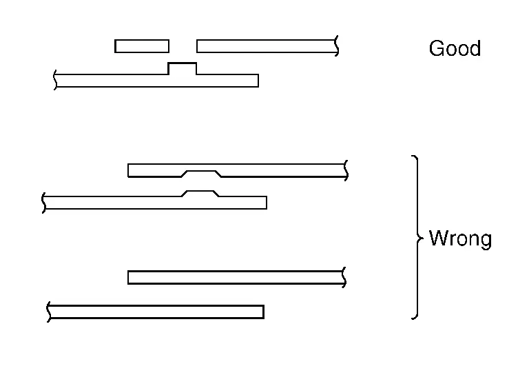
The welding spots should be equally spaced and arranged at the center of the flange to be welded.
(1) CHECK BY USING TEST PIECE (Confirmation before operation)
 NOTE:
NOTE:
Clamp both test pieces together so that they will not slip or move during welding.
(a) Weld together test pieces with the same thickness as the panel to be welded.
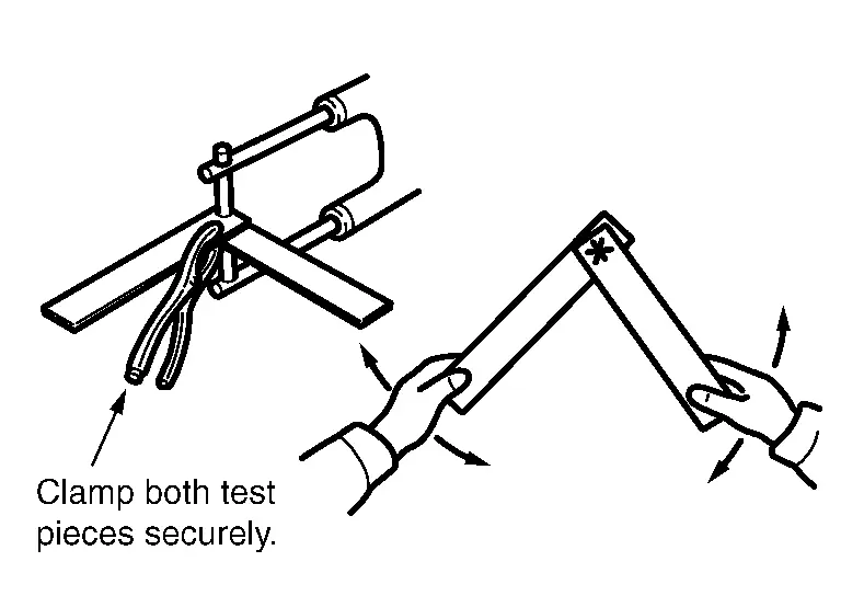
Break the weld by twisting, and examine the break.
(b) With this test, a hole should be made on one test piece by tearing at the welded portion. If no hole is formed, it indicates that the welding conditions are incorrect. Adjust the pressure, welding current, current passing time and other conditions, and repeat test until the best result is obtained.
(2) CHECK BY USING CHISEL AND HAMMER (Confirmation after welding)
(a) Insert a chisel tip between the welded panels, and tap the end until a clearance 3 mm - 4 mm (0.12 in - 0.16 in) [when the panel thickness is 0.8 mm - 1.0 mm (0.031 in - 0.039 in)] is formed between the panels. If the welded portions do not separate, it indicates that the welding has been done properly.
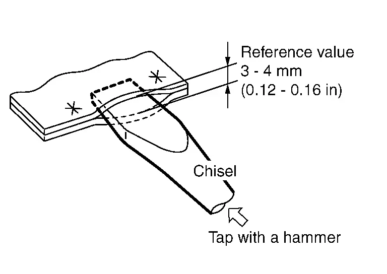
This clearance varies with the location of the welded spots, length of the flange, panel thickness, welding pitch, and other factors. Note that the value shown above is only for reference.
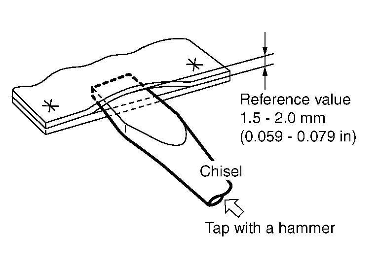
(b) If the thickness of the panels is different, the clearance must be limited to 1.5 mm - 2.0 mm (0.059 in - 0.079 in). Further opening of the panels can become a destructive test.
(c) Be sure to repair the deformed portion of the panel after inspection.
 Precautions when Performing Spot Welding
(1) SELECTION OF SPOT WELDING MACHINE
Use the direct welding method whenever possible.
(When direct welding cannot be applied, use MAG plug welding.)
(2) APPLICATION OF ELECTRODE TIPS
Apply electrode ...
 Mag Welding
MAG welding uses the heat of an electric arc to join two pieces of metal by fusing both the metal and the electrode. For auto repair MAG (Metal Active Gas) are the types of arc welding most often used ...
Other materials:
Adjustment
WARNING:
CAMBER, CASTER
Adjust with the front/rear side adjusting bolts on the lower link.
: Vehicle front
See the following table for the amount of cam bolt scale movement and the variation of camber and caster.
CAUTION:
Align the adjusting bolt cutout with the stamp of lower link bracket. ...
Removal and Installation
WARNING:
REMOVAL
Water pipe 1
Remove engine cover. Refer to Removal and Installation.
Drain engine coolant. Refer to ENGINE COOLANT : Draining.
CAUTION:
Perform this step when the engine is cold.
Remove air inlet tube 1. Refer to Removal & Installation.
Remove water hose 2 and water hose 3 fr ...
RADIATOR : Removal & Installation
WARNING:
REMOVAL
WARNING:
Never remove radiator cap and reservoir tank cap when engine is hot. Serious burns could occur from high-pressure engine coolant escaping from engine cooling system. Wrap a thick cloth around the cap. Slowly turn it a quarter of a turn to release built-up pressure. Carefull ...

0.0052