Exploded View
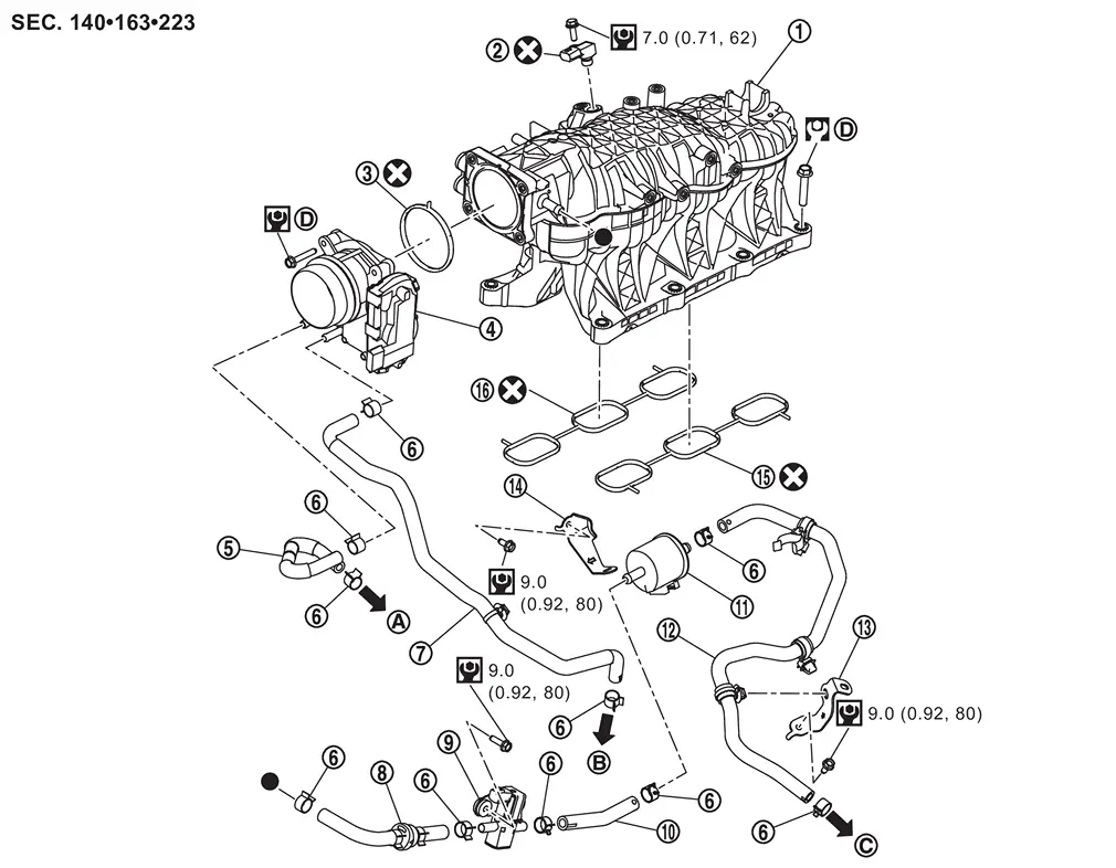
 |
Intake manifold |  |
Manifold absolute pressure sensor |  |
Gasket |
 |
Electric throttle control actuator |  |
Water hose 1 |  |
Clamp |
 |
Water hose 2 |  |
EVAP hose 1 |  |
EVAP canister purge volume control solenoid valve |
 |
EVAP hose 2 |  |
EVAP resonator |  |
EVAP hose 3 |
 |
Bracket 1 |  |
Bracket 2 |  |
Gasket (bank 2) |
 |
Gasket (bank 1) | ||||
 |
To multi-way control valve. Refer to MULTI-WAY CONTROL VALVE : Exploded View. |  |
To turbocharger assembly (bank 2). Refer to Exploded View. |  |
To EVAP canister. Refer to EVAP CANISTER : Exploded View. |
 |
Comply with the assembly procedure when tightening. Refer to Removal and Installation. | ||||
 |
: N·m (kg-m, ft-lb) | ||||
 |
: N·m (kg-m, in-lb) | ||||
 |
: Always replace after every disassembly. | ||||
 |
: Indicates that the parts is connected at points with same symbols in actual vehicle. | ||||
Removal and Installation
WARNING:
Jacking up or lift up the vehicle may the vehicle height to go down which cause a personal injury and/or damage to the air suspension component parts. Refer to Precaution for when Jacking and Lifting Up the vehicle with Electronic Air Suspension System.
REMOVAL
Remove engine cover. Refer to Removal and Installation.
Remove air inlet tube (1 and 2). Refer to Removal & Installation.
Remove electric throttle control actuator as follows:Drain engine coolant from radiator or attach plug to prevent engine coolant leakage when engine coolant is not drained. Refer to ENGINE COOLANT : Draining.
CAUTION:
-
Perform this step when engine is cold.
-
Never spill engine coolant on drive belt.
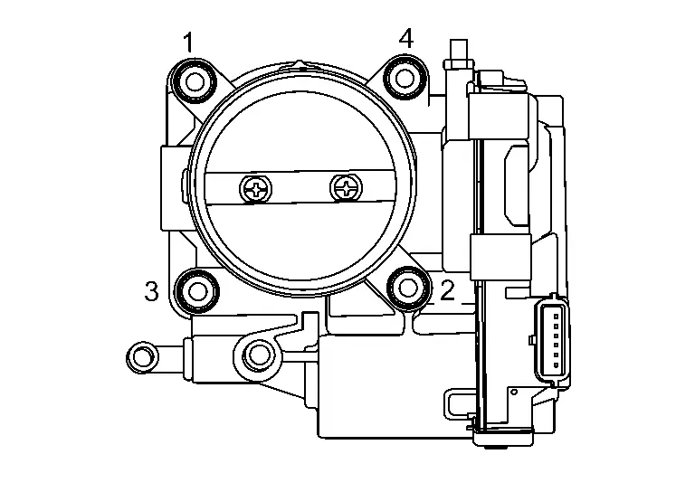
CAUTION:
Handle carefully to avoid any shock to electric throttle control actuator.
 NOTE:
NOTE:
The figure shows the electric throttle control actuator viewed from the air inlet tube 2 side.
Remove gasket.Disconnect blow-by hose 1 (bank 1) and blow-by hose 2 (bank 1) and EVAP hose 1 from intake manifold.
Remove EVAP canister purge volume control solenoid valve harness connector.
Remove EVAP resonator and bracket 2.
Disconnect the manifold absolute pressure sensor harness connector.
Remove blow-by hose 1 (bank 1) and blow-by hose 2 (bank 1).
Loosen mounting bolts in the order from 8 to 1 as shown in the figure to remove intake manifold.
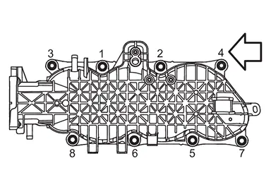
| : Engine front |
Remove gasket (bank 1 and bank 2).
Remove following parts, if necessary.
-
Manifold absolute pressure sensor
-
EVAP canister purge volume control solenoid valve
INSTALLATION
Note the following, and install in the reverse order of removal.
Intake Manifold
-
Tighten mounting bolts to the torque specified below in the order from 1 to 8 as shown in the figure.
: 25.0 N·m (2.6 kg-m, 18 ft-lb) : Engine front
Electric Throttle Control Actuator
-
Tighten to the torque specified below in the order from 1 to 4 as shown in the figure.
: 9.0 N·m (0.92 kg-m, 80 in-lb) NOTE:
The figure shows the electric throttle control actuator viewed from the air inlet tube 2 side.
-
Perform the “Idle Air Volume Learning� and “Throttle Valve Closed Position Learning� when harness connector of electric throttle control actuator is disconnected.
-
Idle Air Volume Learning: Refer to Work Procedure.
-
Throttle Valve Closed Position Learning: Refer to Work Procedure.
-
Inspection
INSPECTION AFTER REMOVAL
Surface Distortion
-
Check the surface distortion of the intake manifold mating surface with a straightedge (A) and a feeler gauge (B) (commercial service tool).
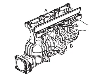
Limit : Refer to Intake Manifold. -
If it exceeds the limit, replace intake manifold.
Other materials
Windshield deicer
Example
The Nissan Armada windshield deicer is specifically designed to remove ice buildup
from the lower windshield area, especially when wiper blades are frozen to the glass.
To activate the deicer in the Nissan Armada, start the engine and press the corresponding
switch. The indicator l ...
Interior lights
Basic information
CAUTION
In the Nissan Armada, avoid leaving interior lights switched on for extended
periods when the engine is not running, as this may lead to battery discharge.
Always switch off all interior lighting before leaving the Nissan Armada
to preserve battery life and ens ...
Panic Alarm Function Does Not Operate
Description
Panic alarm does not operate when press the PANIC ALARM button of Intelligent Key.
Diagnosis Procedure
CHECK INTELLIGENT KEY SYSTEM (REMOTE KEYLESS ENTRY FUNCTION)
Press the LOCK button of Intelligent Key.
Are all doors LOCKED?
YES>>
GO TO 2.
NO>>
Check Intelligent Key syst ...