Diagnosis and Repair Workflow
Work flow
OVERALL SEQUENCE
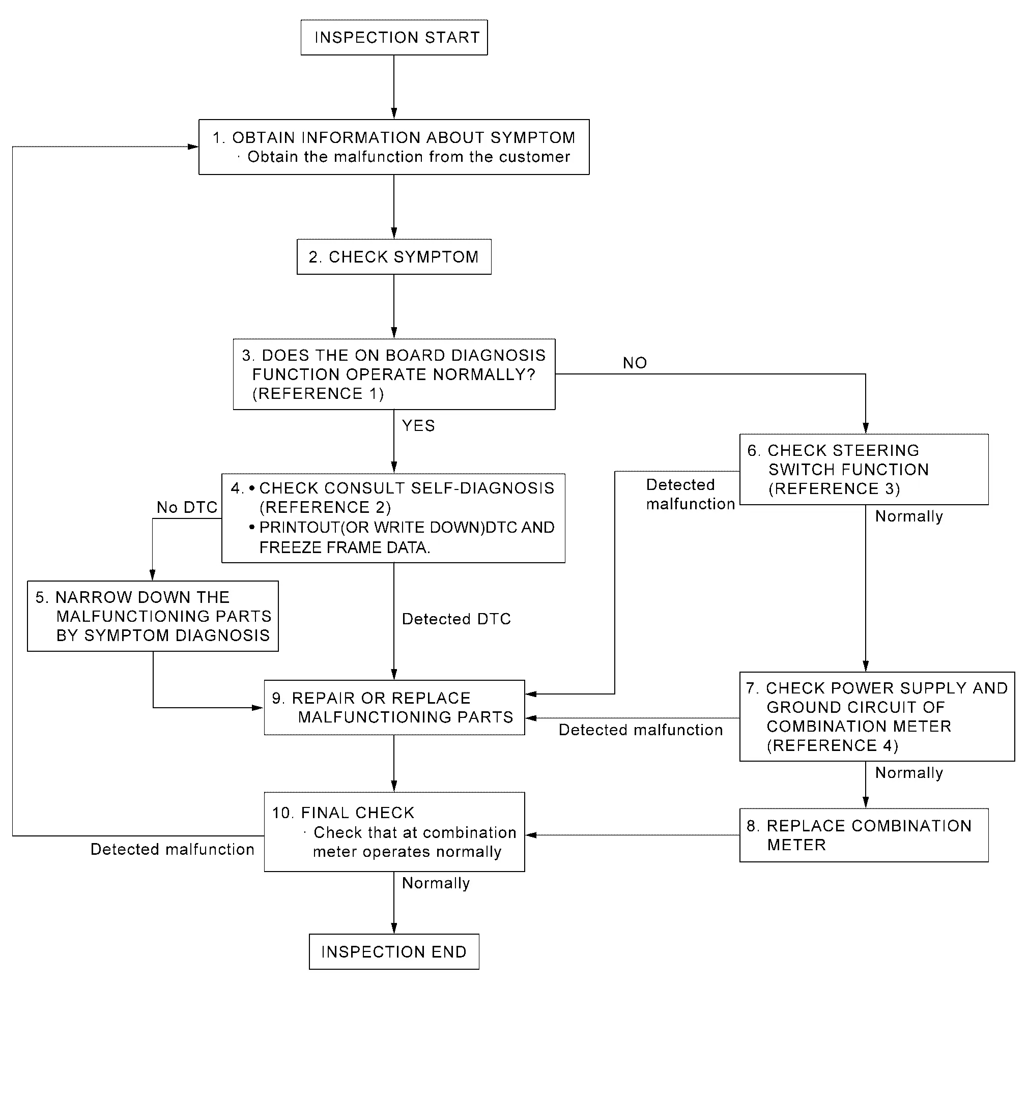
-
Reference 1···On Board Diagnosis Function.
-
Reference 2···DTC Index.
-
Reference 3···Component Function Check.
-
Reference 4···Diagnosis Procedure.
DETAILED FLOW
OBTAIN INFORMATION ABOUT SYMPTOM
Interview the customer to obtain as much information as possible about the conditions and environment under which the malfunction occurred.
>>
GO TO 2.
CHECK SYMPTOM
-
Check the symptom based on the information obtained from the customer.
-
Check that any other malfunctions are present.
>>
GO TO 3.
CHECK ON BOARD DIAGNOSIS OPERATION
Check that the on board diagnosis function operates. Refer to On Board Diagnosis Function.
Does the on board diagnosis function operate normally?
YES>>GO TO 4.
NO>>GO TO 6.
CHECK CONSULT SELF-DIAGNOSIS RESULTS
-
Connect CONSULT and perform self-diagnosis. Refer to DTC Index.
-
When DTC is detected, follow the instructions below:
-
Record DTC and Freeze Frame Data.
-
Are self-diagnosis results normal?
YES>>GO TO 5.
NO>>GO TO 9.
NARROW DOWN THE MALFUNCTIONING PARTS BY SYMPTOM DIAGNOSIS
Perform symptom diagnosis and narrow down the malfunctioning parts.
>>
GO TO 9.
CHECK STEERING SWITCH FUNCTION
Check steering switch function. Refer to Component Function Check.
Is inspection result normal?
YES>>GO TO 7.
NO>>GO TO 9.
CHECK COMBINATION METER POWER SUPPLY AND GROUND CIRCUITS
Check combination meter power supply and ground circuits. Refer to Diagnosis Procedure.
Is inspection result normal?
YES>>GO TO 8.
NO>>GO TO 9.
REPLACE COMBINATION METER
Replace combination meter.
>>
GO TO 10.
REPAIR OR REPLACE MALFUNCTIONING PARTS
Repair or replace the malfunctioning parts.
 NOTE:
NOTE:
If DTC is displayed, erase DTC after repair or replace malfunctioning parts.
>>
GO TO 10.
FINAL CHECK
Check that the combination meter operates normally.
Do they operate normally?
YES>>INSPECTION END
NO>>GO TO 1.
Additional Service When Replacing Combination Meter
Work Procedure
DESCRIPTION
When replacing the Combination meter, perform the procedures before and after replacement.
Before Replacement
Take note the odometer mileage of the combination meter. When replacing the combination meter, check that DTC’s are not detected at "self-diagnostic result" of ABS. When detecting DTC’s, perform "self-diagnostic result" of ABS.
After Replacement
After replacing the combination meter, the following items must be performed.
-
Configuration
-
Actual driving 1 km or more
NOTE:
The odometer mileage of the combination meter is also stored and memorized in the ABS actuator and electric unit (control unit). When driving 1 km or more after replacement of the combination meter, the memorized mileage in the ABS actuator and electric unit (control unit) is written into the new combination meter.
WORK PROCEDURE
COMBINATION METER CONFIGURATION
Perform the combination meter configuration with CONSULT. Refer to Work Procedure.
>>
GO TO 2.
PERFORM SELF-DIAGNOSIS
Perform the self-diagnosis of combination meter with CONSULT. Check if any DTC is detected.
Is any DTC detected?
YES>>Perform the trouble diagnosis for the detected DTC. Refer to DTC Index.
NO>>GO TO 3.
DRIVING TEST
Drive the vehicle on the road 1 km or more.
Check that the odometer shows more than the mileage taken note before.
>>INSPECTION END
Configuration (combination Meter)
Description
Vehicle specification needs to be written with CONSULT because it is not written after replacing the combination meter.
The configuration requires network connection. CONSULT connects to network and then it downloads the configuration data from the server. Then CONSULT writes the vehicle specification to the combination meter.
Refer to Work Procedure.
NOTE:
For details the network connection and operation, refer to “CONSULT Operation Manual�.
The configuration no need to “save� configuration data from the combination meter. The configuration data is always generated freshly at the server and then downloaded to the CONSULT.
CAUTION:
-
Complete the procedure of “Configuration� in order.
-
If incorrect “Configuration�, incidents might occur.
-
Never perform “Configuration� except for new combination meter.
Work Procedure
WRITING VEHICLE SPECIFICATION
With CONSULT
Perform writing vehicle specification to combination meter following "Automatic Configuration" procedure of "Configuration" according to CONSULT Operation Manual.
NOTE:
-
Log in the network according to CONSULT guidance.
-
For details the network connection and operation, refer to “CONSULT Operation Manual�.
>>
WORK END
Other materials
Body Side Welt
Removal and Installation
CAUTION:
Never excessively pull body side welt.
Never damage the body panel.
REMOVALFront Body Side WeltPull the mounting part inside the vehicle to the outside of the vehicle, and then remove front body side welt. CAUTION:
Remove the headlining portion of front body ...
Front Heated Seat System
Symptom Table
Symptom Possible causeInspection item
Front heated seat system does not operate
Only the display unit operation does not operate
Check AV system
Display unit and multifunction switch operation does not operate
Fuse
Front seat heater power supply/ground/LIN signal circuit
Front seat ...
Rear Wheel House Protector
Exploded View
Rear wheel house protector
Grommet
U nut
Removal and Installation
WARNING:
REMOVALRemove rear wheel house protector mounting bolts, nuts, and fixing clips, and then remove rear wheel house protector.
Remove U nut from rear wheel house protector.INSTALLATIONInstall in ...