Precautions for Removing Battery Terminal
-
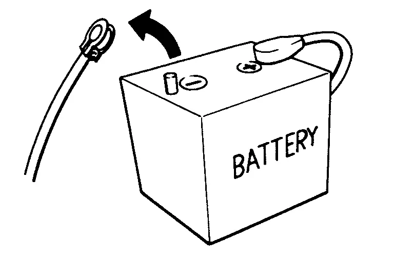
When disconnecting the 12V battery terminal, turn off the ACC power before disconnecting the 12V battery terminal, observing “How to disconnect 12V battery terminal� described below.
 NOTE:
NOTE:
Some ECUs operate for a certain fixed time even after ignition switch is turned OFF and ignition power supply is stopped. If the battery terminal is disconnected before ECU stops, accidental DTC detection or ECU data damage may occur.
-
For Nissan Armada vehicles with the 2-batteries, be sure to connect the main battery and the sub battery before turning ON the ignition switch.
NOTE:
If the ignition switch is turned ON with any one of the terminals of main battery and sub battery disconnected, then DTC may be detected.
-
After installing the 12V battery, always check "Self Diagnosis Result" of all ECUs and erase DTC.
NOTE:
The removal of 12V battery may cause a DTC detection error.
HOW TO DISCONNECT 12V BATTERY TERMINAL
Disconnect 12V battery terminal according to instruction described below.
-
Open the hood.
-
Turn ignition switch to the ON position.
-
Turn ignition switch to the OFF position with the driver side door opened.
-
Get out of the vehicle and close the driver side door.
-
Wait at least 3 minutes. For vehicle with the engine listed below, remove the battery terminal after a lapse of the specified time.
BR08DE : 4 minutes R9N engine : 12 minutes BR10DE : 12 minutes V9X engine : 4 minutes D4D engine : 20 minutes YD25DDTi : 2 minutes HR09DET : 12 minutes YS23DDT : 4 minutes HR10DDT : 12 minutes YS23DDTT : 4 minutes HR10DET : 12 minutes ZD30DDTi : 60 seconds HR13DDT : 12 minutes ZD30DDTT : 60 seconds HRA2DDT : 12 minutes K9K engine : 4 minutes M9R engine : 4 minutes R9M engine : 4 minutes CAUTION:
While waiting, never operate the vehicle such as locking, opening, and closing doors. Violation of this caution results in the activation of ACC power supply according to the Auto ACC function.
-
Remove 12V battery terminal.
CAUTION:
After installing 12V battery, always check self-diagnosis results of all ECUs and erase DTC.
Precaution for when Jacking and Lifting Up the Vehicle with Electronic Air Suspension System
WARNING:
-
When jacking up or lift up the vehicle, always turn OFF the electronic air suspension function with the vehicle unladen and normal height, since the suspension may accidentally move and it can lead to personal injury.
-
When removing the air suspension component parts, always follow the removing procedure since the vehicle height may accidentally drop and it can lead to personal injury.
CAUTION:
When jacking up or lift up the vehicle, always turn OFF the electronic air suspension function with the vehicle unladen and normal height to prevent damage to the air suspension component parts.
OPERATION PROCEDURE
Jacking up or lift up using the following steps.
-
Start engine.
-
Turn auto height mode control switch to ON, shift the shift position to N and set to normal height.
-
Turn OFF the electronic air suspension function. Refer to Operation.
-
Stop engine.
-
Jacking up or lift up.
Precaution for Electronic Air Suspension System
WARNING:
-
When removing the air suspension component parts, always follow the removing procedure since the vehicle height may accidentally drop and it can lead to personal injury.
CAUTION:
-
Never expand and contract the air spring of shock absorber.
-
Never expand and contract the air spring.
-
Never let foreign materials entered into parts.
-
Always check for the air leakage with soapy water after working.
-
Be sure to close the hood after working.
-
Turn ON the electronic air suspension function after working. Refer to Operation.
-
Air suspension component parts may be rusted if de-icer is put in excessively to prevent freezing because it cannot remove moisture in pneumatic circuit.
-
Replacing suspension component parts other than genuine parts may cause low performance of air suspension and calibration failure.
Service Notice or Precautions for Front Final Drive
-
Use recommended gear oil only .Refer to Fluids and Lubricants.
-
Check for the correct installation status prior to removal or disassembly. If matching marks are required, be certain they never interfere with the function of the parts when applied.
-
Overhaul should be done in a clean work area, it is preferable to work in dustproof area.
-
Before disassembly, using steam or white gasoline, completely remove sand and mud from the exterior of the unit, preventing them from entering into the unit during disassembly or assembly.
-
Check appearance of the disassembled parts for damage, deformation, and unusual wear. Replace them with a new ones if necessary.
-
Gaskets, seals and O-rings should be replaced any time when the unit is disassembled.
-
In principle, tighten bolts or nuts gradually in several steps working diagonally from inside to outside. If tightening sequence is specified, observe it.
-
Clean and flush the parts sufficiently and blow-dry them.
-
Be careful not to damage sliding surfaces and mating surfaces.
-
When applying sealant, remove the old sealant from the mounting surface; then remove any moisture, oil, and foreign materials from the application and mounting surfaces.
-
Always use shop paper for cleaning the inside of components.
-
Never use cotton gloves or shop rags to prevent entering of lint.
-
During assembly, observe the specified tightening torque, and apply new gear oil, petroleum jelly, or multi-purpose grease as specified for each vehicle, if necessary.
Other materials
Biometric cooling
Example
The Nissan Armada features an advanced Biometric Cooling system that utilizes
an infrared (IR) sensor to intelligently monitor passenger surface temperature and
automatically adjust airflow for enhanced comfort. This innovative technology allows
the Nissan Armada to dynamically ad ...
Precautions for Removing Battery Terminal
PRECAUTIONS FOR REMOVING BATTERY TERMINAL : Precautions
When disconnecting the 12V battery terminal, turn off the ACC power before disconnecting the 12V battery terminal, observing “How to disconnect 12V battery terminal� described below.
NOTE:
Some ECUs operate for a certain fixed time ev ...
Front Seat Belt
Exploded View
Anchor bolt
Retaining washer
Seat belt adjuster LH
Seat belt adjuster RH
Shoulder anchor LH
Shoulder anchor RH
Spacer
Seat belt pre-tensioner retractor LH
Seat belt pre-tensioner retractor RH
Lap pre-tensioner LH
Lap pre-tensioner RH
Seat belt buck ...