Brake Pad
Inspection and Adjustment
WARNING:
-
Jacking up or lift up the vehicle may the vehicle height to go down which cause a personal injury and/or damage to the air suspension component parts. Refer to Precaution for when Jacking and Lifting Up the vehicle with Electronic Air Suspension System.
INSPECTION
Check brake pad wear thickness from an inspection hole on cylinder body. Check using a scale if necessary.
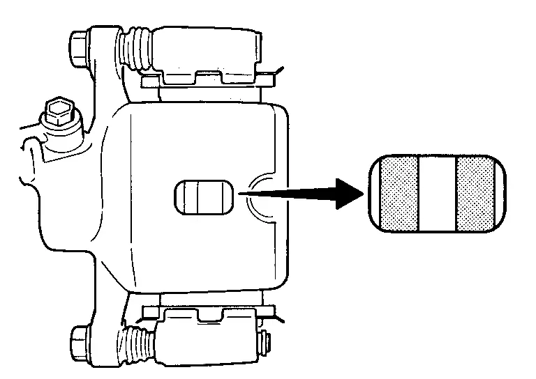
| Wear thickness | : Refer to Rear Disc Brake. |
ADJUSTMENT
Burnish contact surfaces between disc rotor and brake pads according to the following procedure after refinishing or replacing brake pads, or if a soft pedal occurs at very low mileage.
CAUTION:
-
Be careful of vehicle speed because the brake does not operate firmly/securely until pads and disc rotor are securely fitted.
-
Only perform this procedure under safe road and traffic conditions. Use extreme caution.
Drive vehicle on straight, flat road.
Depress brake pedal with the power to stop vehicle within 3 to 5 seconds until the vehicle stops.
Drive without depressing brake for a few minutes to cool the brake.
Repeat steps 1 to 3 until pad and disc rotor are securely fitted.
Disc Rotor
Inspection and Adjustment
WARNING:
-
Jacking up or lift up the vehicle may the vehicle height to go down which cause a personal injury and/or damage to the air suspension component parts. Refer to Precaution for when Jacking and Lifting Up the vehicle with Electronic Air Suspension System.
INSPECTION
Appearance
Check surface of disc rotor for uneven wear, cracks, and serious damage. Replace it if necessary.
Refer to Removal and Installation
Runout
Fix the disc rotor to the wheel hub and bearing assembly with wheel nuts (2 points at least).
Check the wheel bearing axial end play.
Refer to Inspection
Inspect the runout with a dial indicator to measure at 10 mm (0.39 in) inside the disc edge.
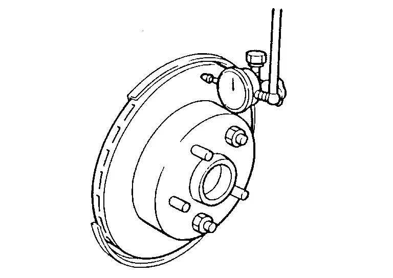
| Runout (with it attached to the vehicle) | : Refer to Rear Disc Brake. |
Find the installation position that has a minimum runout by shifting the disc rotor-to-wheel hub and bearing assembly installation position by one hole at a time if the runout exceeds the limit value.
Refinish the disc rotor if the runout is outside the limit even after performing the above operation.
CAUTION:
-
Check in advance that the thickness of the disc rotor is wear thickness + 0.3 mm (0.012 in) or more.
-
If the thickness is less than wear thickness + 0.3 mm (0.012 in), replace the disc rotor.
Refer to Removal and Installation
| Wear thickness | : Refer to Rear Disc Brake. |
Thickness
Check the thickness of the disc rotor using a micrometer. Replace the disc rotor if the thickness is below the wear limit.
Refer to Removal and Installation
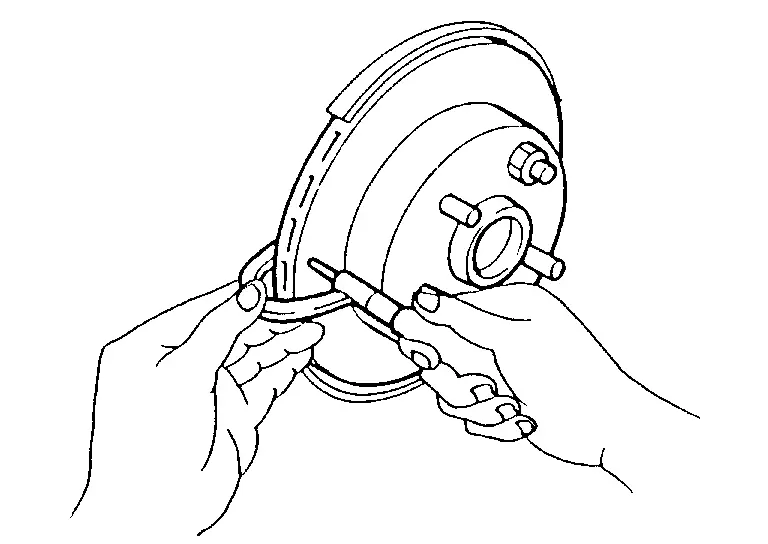
| Wear thickness | : Refer to Rear Disc Brake. |
ADJUSTMENT
Burnish contact surfaces between disc rotors and brake pads according to the following procedure after refinishing or replacing disc rotor, or if a soft pedal occurs at very low mileage.
CAUTION:
-
Be careful of vehicle speed because the brake does not operate firmly/securely until pad and disc rotor are securely fitted.
-
Only perform this procedure under safe road and traffic conditions. Use extreme caution.
Drive vehicle on straight, flat road.
Depress brake pedal with the power to stop vehicle within 3 to 5 seconds until the vehicle stops.
Drive without depressing brake for a few minutes to cool the brake.
Repeat steps 1 to 3 until pad and disc rotor are securely fitted.
Other materials
Precautions. General Precautions
Description
Observe the following precautions to ensure safe and proper servicing. These precautions are not described in each individual section.
Precaution for Supplemental Restraint System (SRS) "AIR BAG" and "SEAT BELT PRE-TENSIONER"
The Supplemental Restraint System such as “AIR BAG� and †...
Front Lower Link
Exploded View
Frame
Stopper rubber
Axle housing
Front lower link
Eccentric disc
Adjusting bolt
: Always replace after every disassembly.
: N·m (kg-m, ft-lb)
Removal and Installation
REMOVALWithout Dynamic Digital Suspension and Electronic Air SuspensionRemove tires. Ref ...
Additional Service When Replacing Driving Video Recorder Control Module
Work Procedure
DRIVING VIDEO RECORDER CONTROL MODULE REPLACEMENT
Replace driving video recorder control module. Refer to Removal and Installation.
>>
GO TO 2.
WRITING OF VIN DATA TO DRIVING VIDEO RECORDER CONTROL MODULE
With CONSULT
Ignition switch ON and wait at least 5 seconds.
Select ...