Exploded View
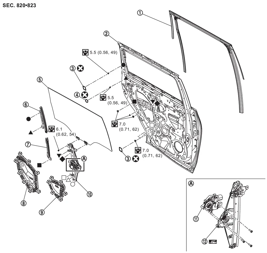
 |
Rear door glass run |  |
Rear door panel |  |
Hole seal 1 |
 |
Hole seal 2 |  |
Rear door glass |  |
Rear door lower sash upper |
 |
Rear door lower sash lower |  |
Rear door inner frame rear |  |
Rear door inner frame front |
 |
Rear door regulator assembly |  |
Rear door power window motor |  |
Rear door regulator |
 |
: Clip | ||||
 |
: Always replace after every disassembly. | ||||
 |
: N·m (kg-m, in-lb) | ||||
 |
: Body grease | ||||
 , , , ,  , ,  , ,  , ,  , ,  , ,  : Indicates that the part is connected at points with same symbol in actual vehicle. : Indicates that the part is connected at points with same symbol in actual vehicle. |
|||||
Rear Door Glass
Removal and Installation
REMOVAL
CAUTION:
Never damage rear door glass and rear door panel.
Remove rear door glass run. Refer to Removal and Installation.
Remove rear door lower sash upper and rear door lower sash lower. Refer to Removal and Installation.
Remove hole seal 1 from rear door panel.
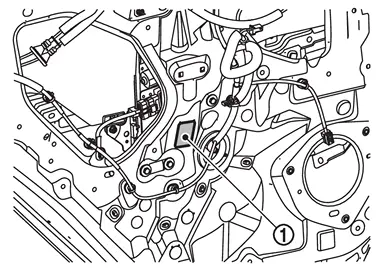
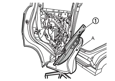
Reconnect power window switch connector with rear door finisher.
 NOTE:
NOTE:
The rear door finisher is big and heavy component. When reconnect it, use the chair/similar something (A) to support rear door finisher as shown in the figure.
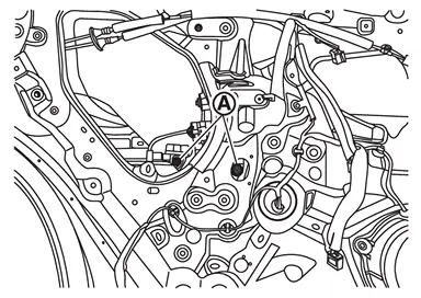
Operate power window switch to raise or lower rear door glass until rear door glass mounting bolts  can be seen, and then remove rear door glass mounting bolts.
Pull up rear door glass to upward, and then remove rear door glass.
CAUTION:
Never damage rear door glass and rear door panel.
INSTALLATION
Note the following items, and then install in the reverse order of removal.
CAUTION:
-
Tighten rear door glass mounting bolts to the specified torque. Refer to Exploded View.
- Never reuse hole seal. Always replace it with a now one when it is removed.
-
After installing rear door glass, perform inspection and adjustment. Refer to Inspection and Adjustment.
Inspection and Adjustment
SYSTEM INITIALIZATION
Perform additional service for operating the power window control system normally after installing rear door glass. Refer to Work Procedure.
FITTING INSPECTION
-
Check that the glass is fitted securely into the sash groove.
-
Lower the glass slightly [approximately 10 to 20 mm (0.39 to 0.79 in)], and check that the clearance to the sash is parallel. Loosen each mounting bolt to correct the glass position if the clearance between the glass and sash are not parallel.
Rear Door Lower Sash
Removal and Installation
REMOVAL
CAUTION:
Never damage rear door glass and rear door panel.
Remove rear door glass run. Refer to Removal and Installation.
Remove rear door inner frame rear. Refer to Removal and Installation.
Fully close rear door glass.
Remove mounting bolt , and then remove rear door lower sash lower.
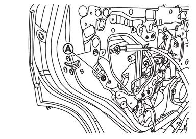
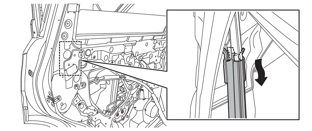
CAUTION:
When removing rear door lower sash lower, disengage fixing portion by arrow direction as shown in the figure.
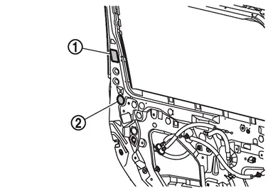
Fully open rear door glass.
Remove hole seal 1 and hole seal 2 from rear door panel.
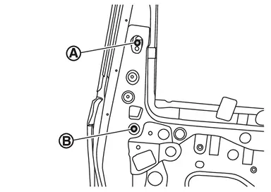
Loosen upper side mounting bolt and remove lower side mounting bolt  , and then remove rear door lower sash upper.
INSTALLATION
Note the following items, and then install in the reverse order of removal.
CAUTION:
-
When installing, insert portion
of rear door lower sash lower to hole of rear door lower sash upper as shown in the figure.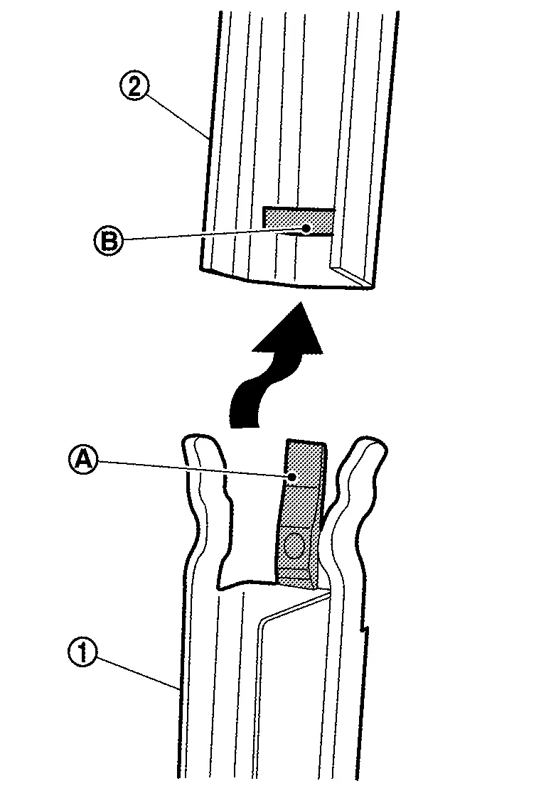
-
Tighten rear door lower sash mounting bolt to the specified torque. Refer to Exploded View.
-
Never reuse hole seal. Always replace it with a new one when it is removed.
-
After installing, check the rear door glass can be move smoothly. If it could not move smoothly, check the rear door glass run and rear door lower sash lower glass run has installed to rear door lower sash lower and upper correctly.
Rear Door Glass Run
Removal and Installation
REMOVAL
CAUTION:
Never excessively pull rear door glass run.
Remove rear door sash cover. Refer to Removal and Installation.
Remove rear door sash inner cover and inside seal. Refer to Removal and Installation.
Reconnect power window main switch connector with rear door finisher.
NOTE:
The rear door finisher is big and heavy component. When reconnect it, use the chair/similar something (A) to support rear door finisher as shown in the figure.
Fully open rear door glass.
Disengage rear door glass run from rear door panel according to numerical order 1→2 indicated by arrows as shown in the figure, and then remove rear door glass run.
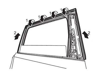
CAUTION:
Should be pulled out slowly to prevent damage rear door glass run.
INSTALLATION
Note the following items, and then install in the reverse order of removal.
CAUTION:
-
When installing rear door glass run between rear door panel/rear door lower sash and rear door glass, make sure engage glass run sash of rear door panel and rear door lower sash.
-
After installing, perform the inspection and adjustment. Refer to Inspection and Adjustment.
Rear Door Inner Frame
Removal and Installation
REMOVAL
CAUTION:
Before removing, take a short memo/photo to remember door harness and cable layout.
Rear Door Inner Frame Front
Remove pull handle bracket. Refer to Removal and Installation.
Apply protective tapes (A) on the part to protect it from damage.
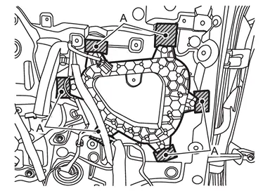
Disengage fixing clips by using removal tool (B), and then remove rear door inner frame front.
Rear Door Inner Frame Rear
Remove rear door finisher. Refer to Removal and Installation.
Disconnect rear door switch harness connector and disengage harness fixing clips.
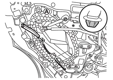
|
: Clip |
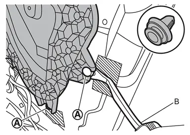
Apply protective tapes (A) on the part to protect it from damage.
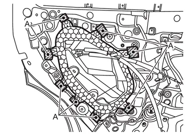
Disengage rear door inner frame rear fixing clips by using removal tool (B).
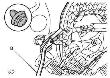
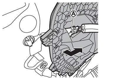
Remove grommet of rear door inside handle cable and rear door lock knob cable , and then remove rear door inner frame rear.
INSTALLATION
Install in the reverse order of removal.
Other materials
Fuel Injector and Fuel Tube
Exploded View
CAUTION:
Never disassemble or remove components beyond the configuration shown in the figure.
Fuel rail pressure sensor
Fuel rail (bank 1)
Stud bolt
Fuel tube insulator
Fuel tube 2
Fuel tube 1
O-ring
Backup ring
Injector holder
Fuel injector
Decoupling ...
Parking Brake Switch
Removal and Installation
REMOVALRemove the instrument lower panel LH. Refer to Removal and Installation.
Remove parking brake switch mounting screws , and then remove parking brake switch .
: Instrument lower panel LH
INSTALLATIONInstall in the reverse order of removal. ...
Refrigeration System Symptoms
Trouble Diagnosis For Unusual Pressure
Diagnose using a manifold gauge whenever system’s high and/or low side pressure(s) is/are unusual. The marker above the gauge scale in the following tables indicates the standard (usual) pressure range. Refer to above table (Ambient air temperature-to-operati ...