
Nissan Armada 2025-2026 Service and Repair Manual: Removal & Installation
WARNING:
Jacking up or lift up the vehicle may the vehicle height to go down which cause a personal injury and/or damage to the air suspension component parts. Refer to Precaution for when Jacking and Lifting Up the Vehicle with Electronic Air Suspension System.
When checking under the vehicle or inside wheel house, always turn OFF the electronic air suspension function with the vehicle unladen and normal height, since the suspension may accidentally move and it can lead to personal injury. Refer to Precaution for Electronic Air Suspension System.
REMOVAL
Drive belt
Remove front under cover, using a power tool (commercial service tool). Refer to Removal and Installation.
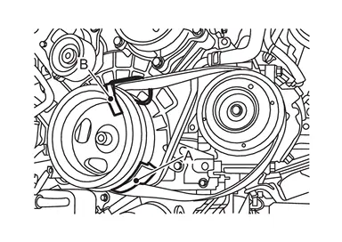
While securely holding the hexagonal part of drive belt auto-tensioner  with a spinner handle (A), move spinner handle in the direction of arrow (loosening direction of drive belt).
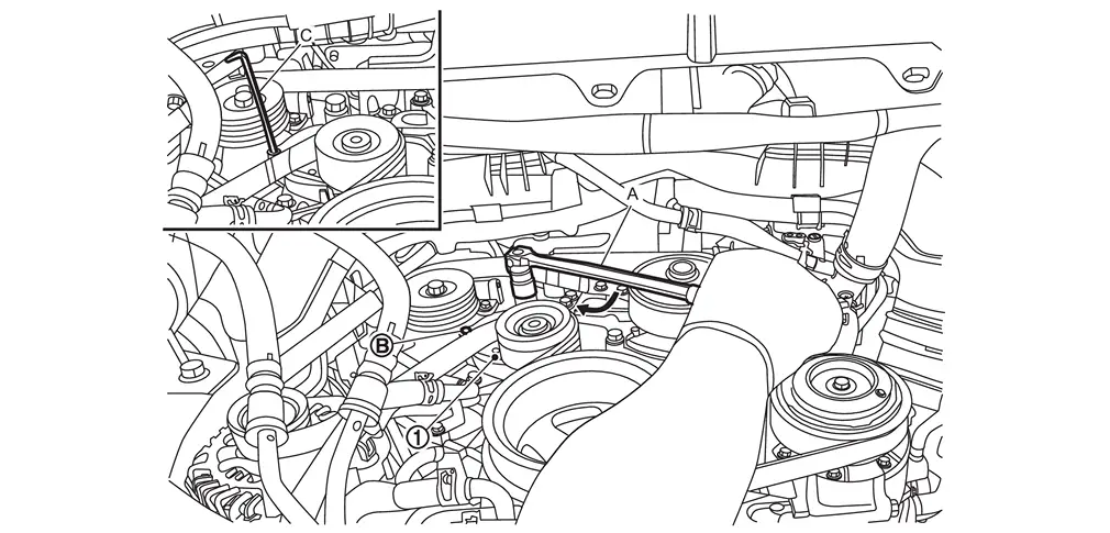
CAUTION:
Never place hand in a location where pinching may occur if the holding tool accidentally comes off.
 | : Holding boss |
| C | : Metallic bar [approximately 6 mm (0.24 in) in diameter]* |
 | : Loosening direction of drive belt |
*: Hexagonal wrench shown as example in the figure
Under the above condition, insert a metallic bar through the holding boss to lock drive belt auto-tensioner pulley arm.
Remove drive belt.
A/C compressor belt
Remove front under cover, using a power tool (commercial service tool). Refer to Removal and Installation.
Remove drive belt.
Cut A/C compressor belt.
INSTALLATION
Drive belt
Note the following, and install in the reverse order of removal.
CAUTION:
Check drive belt is securely installed around all pulleys.
Check drive belt is correctly engaged with the pulley groove.
Check for engine oil and engine coolant are not adhered drive belt and pulley groove.
A/C compressor belt
Install A/C compressor belt as shown below.
CAUTION:
Check for engine oil and engine coolant are not adhered A/C compressor belt and pulley groove.
 NOTE:
NOTE:
Stretch belt service tool is enclosed when A/C compressor belt is ordered.
Attach A/C compressor belt to crankshaft pulley
  and A/C compressor
  as shown in the figure.
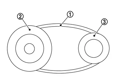
Install A/C compressor belt
between the crankshaft pulley on the crankshaft side and the engine assembly .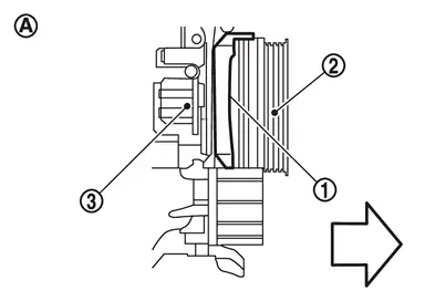

: Vehicle front 
: Side view Install A/C compressor belt
to the A/C compressor .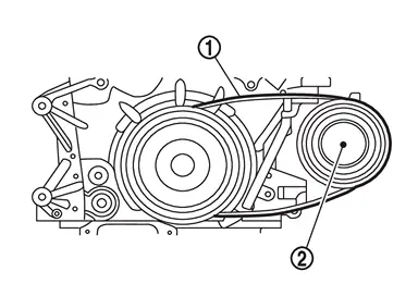
CAUTION:
Make sure that the back side
of the A/C compressor belt faces the engine side.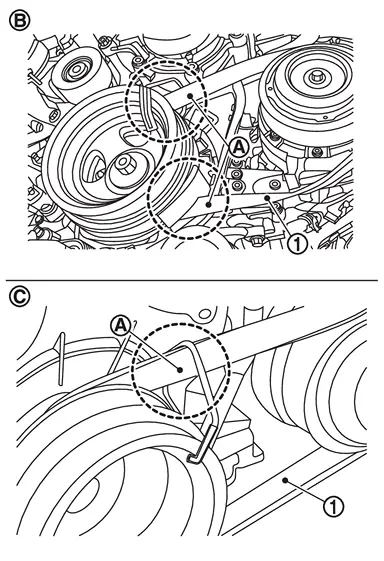
: OK 
: NG
Do not reverse the installation position of the service tool (A).
: A/C compressor belt side : Crankshaft pulley side
When installing to the crankshaft pulley, make sure that the crankshaft pulley protection tube
of the service tool (A) is not inserted too far.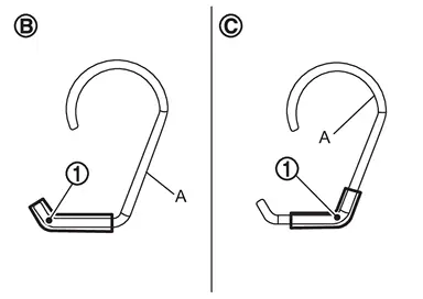
: OK : NG
NOTE:
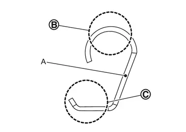
Set the service tool (A) as shown below.
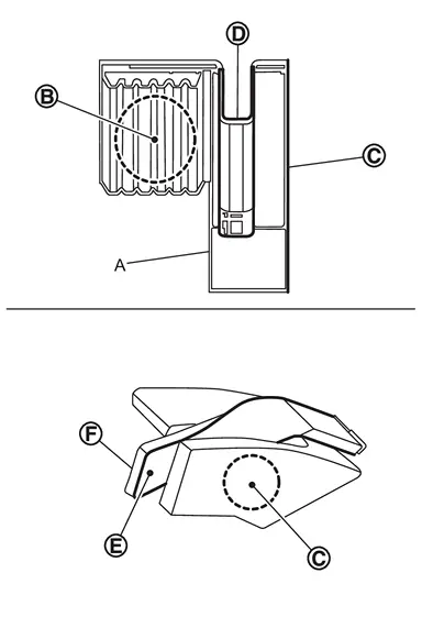
: Crankshaft pulley side : Engine side 
: Belt install part 
: Belt back side 
: Belt groove side
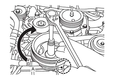
CAUTION:
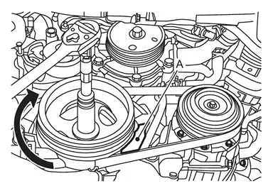
When rotating the crankshaft pulley by applying a tool to the crankshaft pulley bolt, do not turn the crankshaft pulley bolt in the direction of loosening.
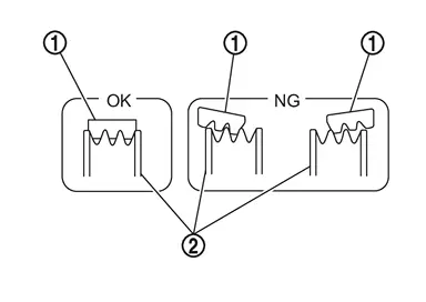
Referring to the figure, check that the A/C compressor belt
is securely attached around the crankshaft pulley .
: OK (Installed correctly.) : NG (A/C compressor belt is misaligned (C) with the groove of the crankshaft pulley.)
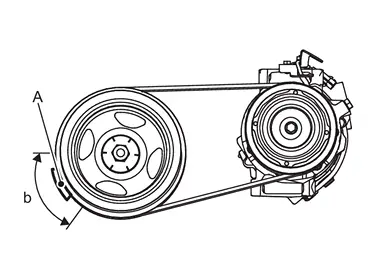
) while making sure that the A/C compressor belt is not misaligned with the pulley groove.
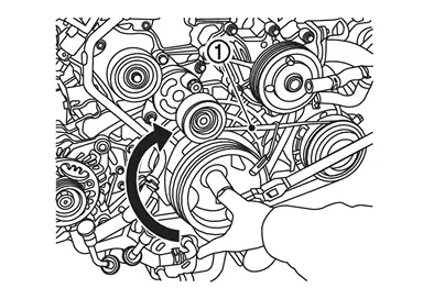
CAUTION:
Check A/C compressor belt is correctly engaged with the pulley groove.
When the service tool (A) is in position (B), remove the service tool (C).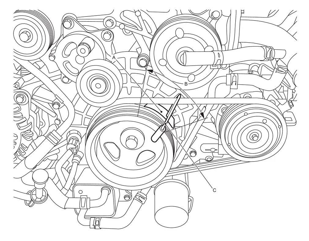
CAUTION:
Be careful not to damage the belt when removing the mounting tool.
Check A/C compressor belt is securely installed around crankshaft pulley and A/C compressor.
: A/C compressor belt : A/C compressor/ Crankshaft pulley
 Exploded View
Idler pulley Alternator Drive belt auto-tensioner Crankshaft pulley A/C compressor Water pump Drive belt A/C compressor belt View Indicator Range when new drive belt is installed Possible ...
 Adjustment
Refer to Drive Belt. ...
Other materials:
Precautions for Body Repair
WARNING:
WARNING:
The repair information in this section is intended for trained body repair technicians who have attained a high level of skill and experience (e.g. ASE Collision Repair Certification, I-CAR Professional Development Program [PDP] training, etc.) in repairing collision damaged vehicl ...
Work Procedure
REPLACE INTELLIGENT KEY UNIT
Replace Intelligent Key unit. Refer to Removal and Installation.
>>
GO TO 2.
WRITING Vehicle SPECIFICATION
CONSULT Configuration
Perform configuration. Refer to Description.
>>
GO TO 3.
REGISTER INTELLIGENT KEYS
CAUTION:
If perform Intelligent Key registr ...
Removal and Installation
REMOVAL
Front Foot Duct LH
Remove instrument lower panel LH and center instrument lower panel. Refer to Removal and Installation.
Remove driver knee air bag module. Refer to Removal and Installation.
Remove side ventilator duct 2 LH. Refer to Removal and Installation.
Remove fixing screws and disen ...

0.0075