
Nissan Armada 2025-2026 Service and Repair Manual: Removal & Installation
WARNING:
REMOVAL
Remove front cover. Refer to Removal & Installation.
Remove timing chain. Refer to Removal and Installation.
Remove fuel tube assembly. Refer to Removal and Installation.
Remove high pressure fuel pump. Refer to Removal & Installation.
Remove camshaft sprockets (INT and EXH).
Secure hexagonal part of the camshaft using a suitable tool, loosen the mounting bolts of INT
 and EXH
  of camshaft sprocket (bank 1 and 2) and remove the camshaft sprockets.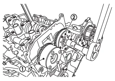
Remove camshaft brackets.
Mark camshafts, camshaft brackets and bolts so they are placed in the same position and direction for installation.
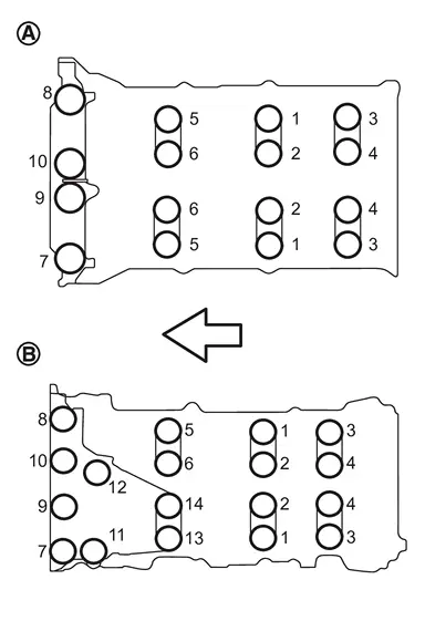
Equally loosen camshaft bracket bolts in several steps in the order from 10 to 1 (bank 1
 ), and for (bank 2
  ), from 12 to 1 as shown in the figure.
 | : Engine front |
Remove camshaft.
Remove valve lifter.
Identify installation positions, and store them without mixing them up.
INSTALLATION
 NOTE:
NOTE:
If an intake camshaft or exhaust camshaft are removed, carry out the teach of “Electric IVT Control Actuator Position Learning. Refer to Work Procedure.
If an intake camshaft sprocket or exhaust camshaft sprocket are removed, carry out the teach of “Electric IVT Control Actuator Position Learning. Refer to Work Procedure.
Install valve lifter.
Install it in the original position.
Install camshafts.
Follow your identification marks made during removal, or follow the identification marks that are present on new camshafts for proper placement and direction.
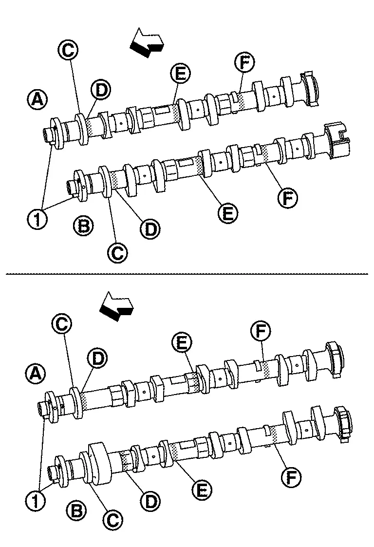
: Engine front Bank INT/EXH Dowel pin Paint marks Identification mark 
M1 
M2 
M3 
1 EXH Yes BLUE NO WHITE NO INT Yes BLUE WHITE NO NO 2 INT Yes BLUE WHITE NO NO EXH Yes BLUE NO WHITE NO Install camshaft so that dowel pin
on front end face are positioned as shown in the figure. (No. 1 cylinder TDC on its compression stroke)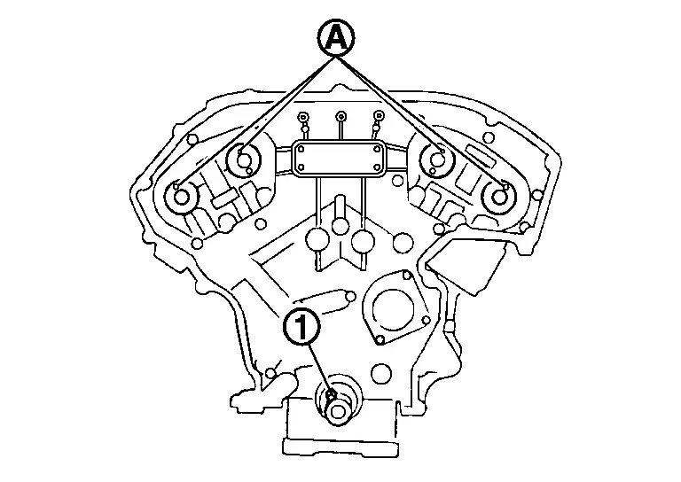
: Crankshaft key NOTE:Though camshaft does not stop at the portion as shown in the figure, for the placement of cam nose, it is generally accepted camshaft is placed for the same direction of the figure.
Install camshaft brackets.
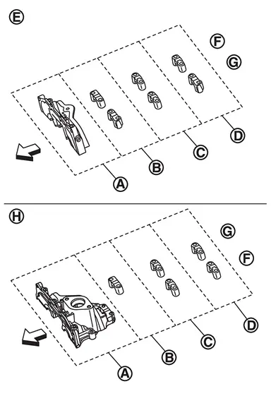
| : No. 1 |
| : No. 2 |
| : No. 3 |
| : No. 4 |
| : Bank 1 |
| : Exhaust side |
 | : Intake side |
 | : Bank 2 |
| : Engine front |
Remove foreign material completely from camshaft bracket backside and from cylinder head installation face.
Install camshaft bracket in original position and direction as shown in figure.
Install camshaft brackets (No. 2 to 4) aligning the stamp marks as shown in the figure.
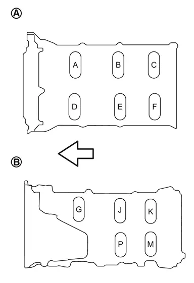
: Bank 1 : Bank 2 : Engine front NOTE:There are no identification marks indicating bank 1 and bank 2 for camshaft bracket (No. 1).
Apply liquid gasket to mating surface of camshaft bracket (No. 1) as shown on both bank 1
and bank 2 .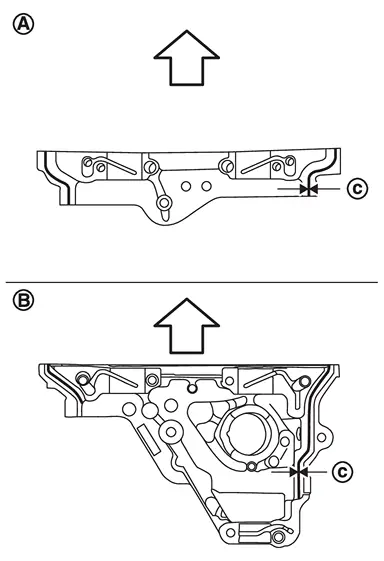
: Engine front 
: φ3.4 - 4.4 mm (0.134 - 0.173 in) CAUTION:
Be sure to wipe off any excessive liquid gasket.
Tighten camshaft bracket bolts in the following steps, as shown in the figure.
| : Bank 1 |
| : Bank 2 |
| : Engine front |
CAUTION:
Do not reuse washers.
Tighten No. 7 to 10 in numerical order as shown. (Bank1)Tighten No. 7 to 14 in numerical order as shown. (Bank2)
 : 1.96 N·m (0.20 kg-m, 17 in-lb) : 1.96 N·m (0.20 kg-m, 17 in-lb) |
| : 1.96 N·m (0.20 kg-m, 17 in-lb) |
Tighten No. 1 to 14 in numerical order as shown. (Bank2)
| : 5.88 N·m (0.60 kg-m, 52 in-lb) |
Tighten No. 1 to 14 in numerical order as shown. (Bank2)
 : 10.1 N·m (1.0 kg-m, 7 ft-lb) : 10.1 N·m (1.0 kg-m, 7 ft-lb) |
Inspect and adjust the valve clearance. Refer to Adjustment.
Install in the reverse order of removal after this step.
 Exploded View
Camshaft bracket (No. 1) (bank 1) Camshaft (EXH) (bank 1) Camshaft (INT) (bank 1) Camshaft bracket Dowel pin Plug Gasket Camshaft signal plate (EXH) Camshaft signal plate (INT) Cylinder hea ...
 Inspection
INSPECTION AFTER REMOVAL
Camshaft Runout
Put V-block on precise flat table, and support No. 2 and 4 journals of camshaft.
CAUTION:
Never support No. 1 journal (on the side of camshaft sprocket) beca ...
Other materials:
Removal and Installation
REMOVAL
CAUTION:
Remove air cleaner body. Refer to Removal and Installation.
Remove mounting bolt , and then disconnect high-pressure flexible hose from condenser inlet pipe.
: Vehicle front
Remove mounting bolt , and then disconnect high-pressure flexible hose from A/C compressor.
: Vehicl ...
Special Service Tools
Tool number
(TechMate No.)
Tool name Description ST35652000
( − )
Shock absorber attachment
Disassembling and assembling shock absorber ST3127S000
(NI-25765-A)
Preload gauge
Measuring rotating torque of ball joint ...
Cold weather driving
Freeing a frozen door lock
To avoid door lock freezing in cold conditions, it is recommended to apply a
suitable deicer into the keyhole of your Nissan Armada before temperatures drop
significantly.
If the lock on your Nissan Armada becomes frozen, gently warm the key before
inserting it int ...

0.0051