
Nissan Armada 2025-2026 Service and Repair Manual: Removal & Installation
WARNING:
REMOVAL
CAUTION:
While electrical brake control unit
 is removed, hold part
  with hand.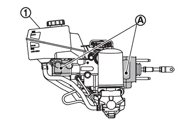
Never disassemble electrical brake control unit.
Never depress brake pedal during removal and installation of brake hose because brake fluid may scatter.
Perform inspection before removal. Refer to Inspection.
Ignition switch OFF and disconnect CONSULT from DDL2 diagnosis connector.
CAUTION:
Never operate the vehicle.
Disconnect negative terminal of 12V battery. Refer to Precautions for Removing Battery Terminal.
Drain brake fluid. Refer to Draining.
Disconnect electrical brake control unit harness connector , follow the procedure below.
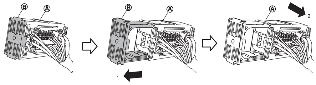
 of the connector toward the direction (1). Disconnect electrical brake control unit harness connector to ward the direction (2).
Disconnect accumulator harness connector, and remove harness clip from electrical brake control unit.
Remove relay box.
Remove brake tubes from electrical brake control unit and ABS actuator and electric unit (control unit).
Move heater hose. Fix heater hose in a place where it will not interfere with work.
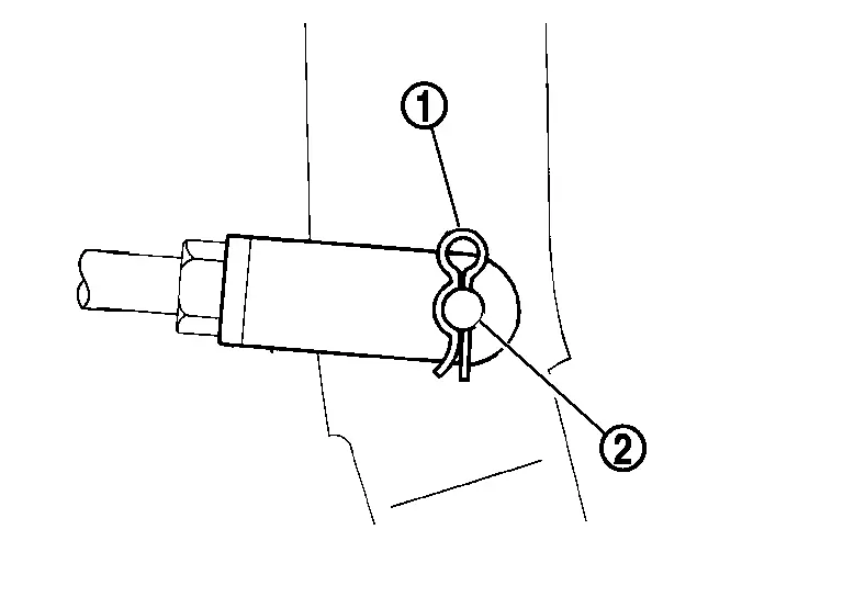
Remove snap pin and clevis pin  from clevis.
Remove electrical brake control unit mounting nut.
Remove electrical brake control unit from vehicle.
CAUTION:
Never deform the brake tube when removing electrical brake control unit.
Remove gaskets and spacer from electrical brake control unit.
Remove brackets from electrical brake control unit if necessary.
Perform inspection after removal. Refer to Inspection.
INSTALLATION
CAUTION:
When installing electrical brake control unit, never deform brake tube.
If electrical brake control unit is dropped or impacted, replace electrical brake control unit assembly.
When installing, hold part
of electrical brake control unit .Never apply grease or lubricant to the parts that contact with brake fluid and rubber parts.
Note the following, and install in the reverse order of removal.
Never crush threads of stud bolts of the electrical brake control unit. When installing diagonally, the dash panel may damage the threads.
Never deform brake tube when installing electrical brake control unit.
Never reuse clevis pin.
Temporarily tighten flare nut of brake tube
by hand, and then install it to the electrical brake control unit to the specified tightening torque using flare nut torque wrench (commercial tool) (A). Refer to Exploded View.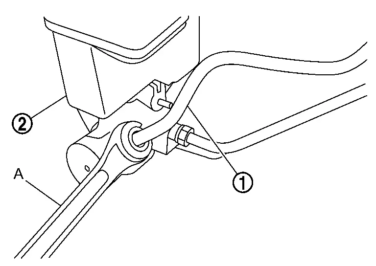
Install electrical brake control unit harness connector
, follow the procedure below.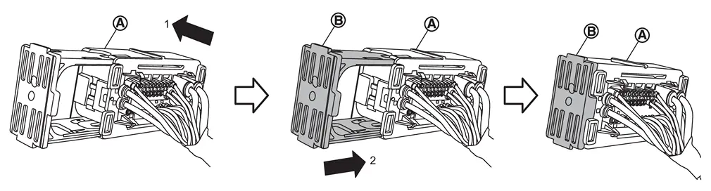
Install electrical brake control unit harness connector toward the direction (1).
Push the lock
of the connector toward the direction (2).
Perform air bleeding. Refer to Work Procedure.
Check brake pedal for each item, adjust when there is deviation from the specified value. Refer to Inspection and Adjustment.
Perform inspection after installation. Refer to Inspection.
After replacing the electrical brake control unit, always follow the disposal procedure to discard the electrical brake control unit. Refer to Disposal.
 Exploded View
Reservoir cap Electrical brake control unit Bracket Caution label Gasket Spacer : N·m (kg-m, ft-lb) : N·m (kg-m, in-lb) : Always replace after every disassembly. ...
 Inspection
INSPECTION BEFORE REMOVAL
Check brake fluid level switch. Refer to Brake Fluid Level Switch.
INSPECTION AFTER REMOVAL
Check the following items, and replace the part if necessary.
Check for damage, de ...
Other materials:
Removal and Installation
REMOVAL
Remove radiator air guide upper. Refer to Removal and Installation.
Remove front combination lamp. Refer to Removal and Installation.
Remove active grille shutter upper side mounting bolts. Refer to Removal and Installation.
Remove hood lock assembly. Refer to Removal and Installation.
Disen ...
Removal and Installation
WARNING:
REMOVAL
Remove tires. Refer to ROAD WHEEL TIRE : Removal & Installation.
Remove stabilizer connecting rod mounting nuts from lower link.
Remove stabilizer clamps mounting bolts, and remove stabilizer assembly from vehicle.
Remove stabilizer clamps, stabilizer bushings, and stabilizer co ...
Basic information
WARNING
Do not allow children to play with seat belts inside the Nissan Armada. Many
seating positions are equipped with Automatic Locking Retractor (ALR) seat belts.
If a belt becomes wrapped around a child’s neck while ALR mode is active, it may
tighten and cause serious injury or dea ...

0.006