
Nissan Armada 2025-2026 Service and Repair Manual: Removal and Installation
WARNING:
REMOVAL
Ignition coil
 NOTE:
NOTE:
No. 2-No. 5 can be removed using only the ignition coil.
Remove engine cover. Refer to Removal and Installation.
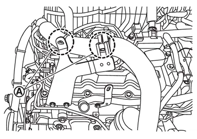
Remove mounting bolt  from air inlet tube 1
  . (No. 1 and No. 6 cylinder)
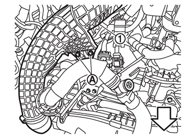
 | : Vehicle front |
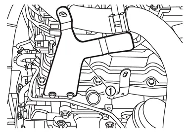
Remove mounting bolt from air inlet tube 1 . (No. 1 and No. 6 cylinder)
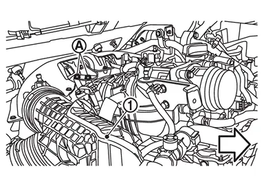
| : Vehicle front |
Remove mounting bolt from air inlet tube 1 . (No. 1 and No. 6 cylinder)
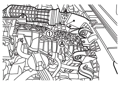
Remove air inlet tube 1 from turbocharger (bank 1 side). (No. 1 and No. 6 cylinder)
Refer to Removal & Installation.
Move air inlet tube 1 to a position where it is easier to work. (No. 1 and No. 6 cylinder)
Remove ignition coil.
CAUTION:
Never shock ignition coil.
Rocker cover
Remove the following parts:
Engine cover: Refer to Removal and Installation.
Air cleaner assembly: Refer to Removal and Installation.
Air inlet tube: Refer to Removal & Installation.
Intake manifold: Refer to Removal and Installation.
Remove bank 1 by following the steps below.Remove ignition coil.
CAUTION:
Never shock ignition coil.
Remove blow-by hose 1 (bank 1) and blow-by hose 2 (bank 1)
  .
.
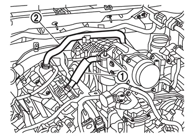
.
.
Remove bank 2 by following the steps below.Remove crankcase ventilation valve and resonator as a set. Remove blow-by hose (bank 2) .
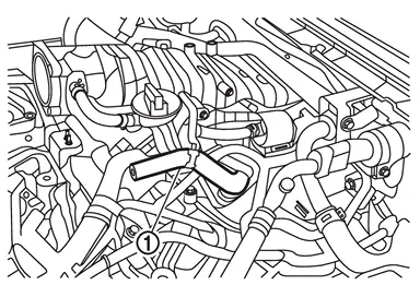
CAUTION:
Never shock ignition coil.
Disconnect the cylinder block heater harness connector from cylinder block. (For CANADA) Disconnect the high pressure fuel pump harness connector. Refer to Removal & Installation. Remove high pressure fuel pump insulator. Refer to Removal & Installation. Disconnect the electric throttle control actuator harness connector. Refer to Exploded View. Disconnect the recirculation valve harness connector. Refer to Exploded View. Disconnect the electric intake valve timing control actuator (bank 2) harness connector. Refer to Exploded View. Disconnect the camshaft position sensor harness connector. (intake and exhaust)Loosen mounting bolts in the order from 10 to 1 (bank 1 ), and for (bank 2  ), from 11 to 1 as shown in the figure.
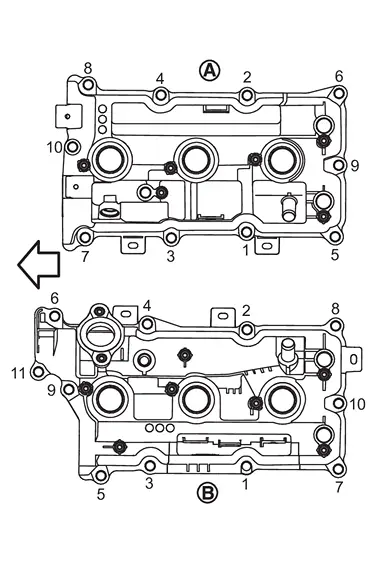
| : Engine front |
Remove rocker cover gasket from rocker cover.
INSTALLATION
NOTE:
If an intake camshaft position sensor or exhaust camshaft position sensor are replaced, carry out the teach of “Electric IVT Control Actuator Position Learning�. Refer to Work Procedure.
Apply liquid gasket to the positions shown.
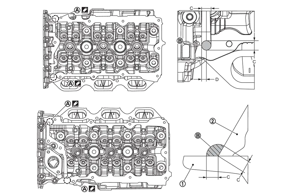
| : Cylinder head |
| : Camshaft bracket (No. 1) |
| C | : 10 mm (0.39 in) |
| D | : 4 mm (0.16 in) (Application position of liquid gasket from the end surface of the camshaft bracket) |
Install the rocker cover using the following steps:
Bank 1 side
Install guide pin in the shown figure 9.
| : Engine front |
| : Bank 1 side |
| : Bank 2 side |
NOTE:
Guide pin are included with the replacement part.
Temporarily tighten the mounting bolts in the order shown in figure 1 to 8.
 : 1.96 N·m (0.2 kg-m, 17 in-lb) : 1.96 N·m (0.2 kg-m, 17 in-lb) |
Remove the guide pin.
Temporarily tighten the mounting bolts in the order shown in figure 9 to 10.
| : 1.96 N·m (0.2 kg-m, 17 in-lb) |
Tighten to the specified torque in the order 1 to 10 shown in the figure.
| : 8.33 N m (0.85 kg-m, 74 in-lb) |
Bank 2 side
Install guide pin in the shown figure 10.
| : Engine front |
| : Bank 1 side |
| : Bank 2 side |
NOTE:
Guide pin are included with the replacement part.
Temporarily tighten the mounting bolts in the order shown in figure 1 to 9.
| : 1.96 N·m (0.2 kg-m, 17 in-lb) |
Remove the guide pin.
Temporarily tighten the mounting bolts in the order shown in figure 10 to 11.
| : 1.96 N·m (0.2 kg-m, 17 in-lb) |
Tighten to the specified torque in the order 1 to 11 shown in the figure.
| : 8.33 N m (0.85 kg-m, 74 in-lb) |
 Exploded View
Bank 1 side
Ignition coil Spark plug Rocker cover Rocker cover gasket Blow-by hose 1 (bank 1) Clamp Blow-by hose 2 (bank 1) Intake camshaft position sensor Exhaust camshaft position sensor ...
 Oil Pan (lower)
...
Other materials:
Work Procedure
Always perform the side radar alignment after performing the following work.
After removing and installing or replacing the side radar.
After removing and installing, replacing or repainting the rear bumper.
Side radar alignment conditions are following;
The vehicle speed is 20 km/h (13 MPH) or hig ...
Inspection
AFTER A COLLISION
WARNING:
To avoid the risk of death or severe injury:
Replace any seat belt assembly (including anchor bolts) if:
Anchor bolts are deformed or worn out.
PRELIMINARY CHECKS
Check the shoulder seat belt guide for third seat. Check that guide swivels freely and that webbing lays flat ...
System maintenance (ProPILOT Assist 2.1)
For reliable and accurate operation of the Nissan Armada ProPILOT Assist 2.1
system, it is crucial to keep the driver monitoring area clean and free from any
obstruction at all times.
Regularly inspect the camera surface and gently remove dust, fingerprints, or
any debris using a soft, cl ...

0.0067