
Nissan Armada 2025-2026 Service and Repair Manual: Removal and Installation
WARNING:
WITHOUT DYNAMIC DIGITAL SUSPENSION AND ELECTRONIC AIR SUSPENSION
Removal
Remove rear tire. Refer to ROAD WHEEL TIRE : Removal & Installation.
CAUTION:
Never depress brake pedal while caliper assembly is removed.
Remove disc rotor.
CAUTION:
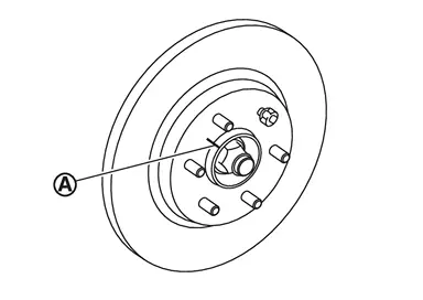
Never drop disc rotor.
Remove wheel sensor harness. Refer to Removal and Installation.
Put matching mark  on drive shaft and wheel hub and bearing assembly.
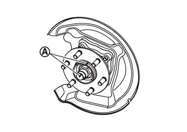
CAUTION:
Use paint or similar substance for matching marks. Never scratch the surface.
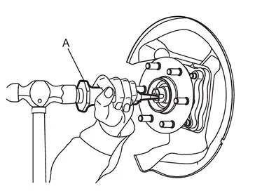
CAUTION:
Completely release the caulking part of the wheel hub lock nut.
Never add damage to the driveshaft side screw thread with wheel hub lock nut.
 NOTE:
NOTE:
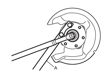
CAUTION:
Never use a power tool.
Set suitable jack under rear lower link.
CAUTION:
Never damage rear lower link.
Check the stable condition when using a jack.
Remove rear lower link and coil spring. Refer to Removal and Installation.
Using jack to front lower link.
Loosen the front lower link frame side bolt.
Remove cotter pin and nut, and remove front lower link from axle housing.
CAUTION:
Never damage ball joint boot.
Remove cotter pin and nut, and remove suspension arm from axle housing.
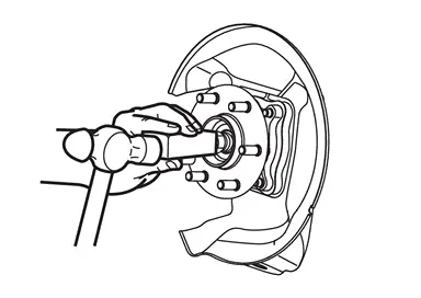
CAUTION:
Never allow drive shaft to hang down without support for counterpart such as joint sub-as- sembly, and other parts.
NOTE:
Remove axle housing assembly.
Remove drive shaft from rear final drive assembly.
Use the drive shaft attachment [SST: KV40107500 ( − )] (A) and a sliding hammer (commercial service tool) (B) while inserting tip of the drive shaft attachment between housing and rear final drive assembly.
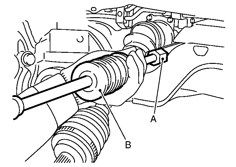
CAUTION:
Never place drive shaft joint at an extreme an- gle when removing drive shaft. Also be careful not to overextend slide joint.
Confirm that the circular clip is attached to the drive shaft.
Use paint or similar substance for matching marks. Never scratch the surface.
Perform inspection after removal. Refer to Inspection.
Installation
WHEEL SIDE
Note the following, and install in the reverse order of removal.
CAUTION:
Never apply lubricating oil to these matching surface.
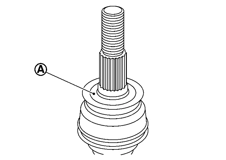
CAUTION:
Apply paste to cover entire flat surface of joint sub-assembly of drive shaft.
Amount paste 1.0 – 3.0 g (0.04 – 0.10 oz) 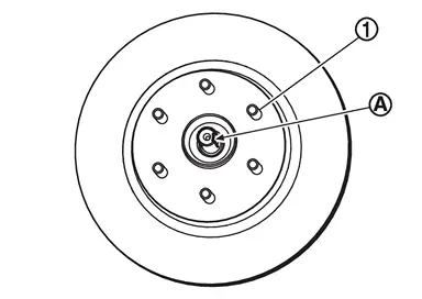
Use the following torque range for tightening the wheel hub lock nut.

: 218 – 223 N·m (22 – 23 kg-m, 161 – 164 ft-lb) CAUTION:
Never reuse wheel hub lock nut.
NOTE: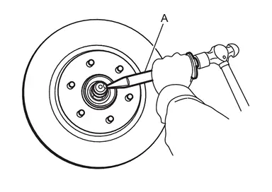 NOTE:
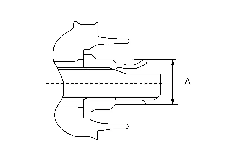
NOTE:Use the following range for stacking the whell hub lock nut.
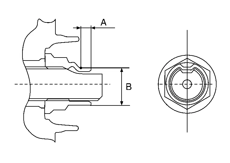
A : 6.2 mm (0.244 in) B : 29.4 – 30.8 mm (1.157 – 1.213 in)
FINAL DRIVE SIDE
Note the following, and install in the reverse order of removal.
CAUTION:
Always replace rear final drive assembly side oil seal with new one when installing drive shaft. Refer to Removal and Installation.
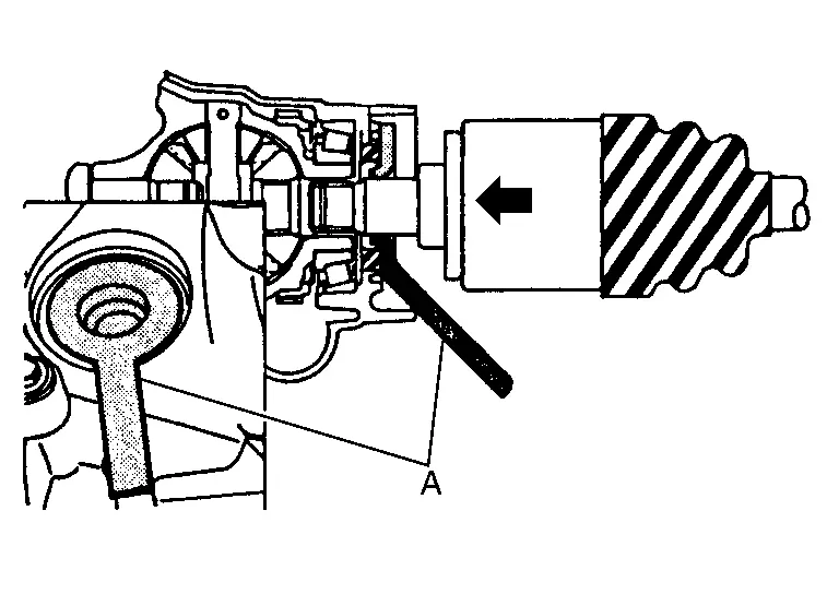
Place the protector [SST: KV38108000 ( - )] (A) onto rear final drive assembly to prevent damage to the rear final drive assembly side oil seal while inserting drive shaft. Slide drive shaft sliding joint and tap with a hammer to install securely.
CAUTION:
Be sure to fully install the protector into the depths of the part.
WARNING:
CAUTION:
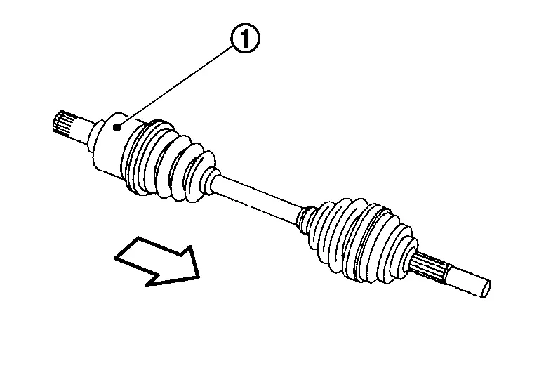

: Wheel side Pull the joint sub-assembly in the axial direction away from rear final drive assembly (arrow). Confirm that the joint sub assembly cannot be pulled out.
WITH DYNAMIC DIGITAL SUSPENSION AND ELECTRONIC AIR SUSPENSION
Removal
Start engine.
Turn OFF the electronic air suspension function. Refer to Operation.
Stop engine.
Lift up the vehicle.
Remove rear tire. Refer to ROAD WHEEL TIRE : Removal & Installation.
CAUTION:
Never depress brake pedal while caliper assembly is removed.
Remove disc rotor.
CAUTION:
Never drop disc rotor.
Remove wheel sensor harness. Refer to Removal and Installation.
Put matching mark on drive shaft and wheel hub and bearing assembly.
CAUTION:
Use paint or similar substance for matching marks. Never scratch the surface.
CAUTION:
Completely release the caulking part of the wheel hub lock nut.
Never add damage to the driveshaft side screw thread with wheel hub lock nut.
NOTE:
CAUTION:
Never use a power tool.
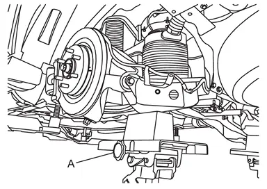
CAUTION:
Never damage rear lower link.
Check the stable condition when using a suitable jack.
Never lower the suitable jack until installation is completed.
Loosen the air connector  and perform air bleeding.
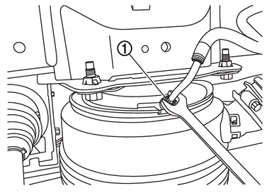
CAUTION:
Be careful since air flows swiftly from air tube.
Loosen the air connector slowly.
Never disconnect the air connector until the air completely bleeds.
Remove air tube together with air connector  from air spring
  .
.
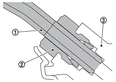
CAUTION:
Never damage air connector, air adapter, and air tube.
When reusing air connector, never remove air tube from air connector.
NOTE:
Remove rear lower link from axle housing. Refer to Removal and Installation.
Using jack to front lower link.
Loosen the front lower link frame side bolt.
Remove cotter pin and nut, and remove front lower link from axle housing.
Remove cotter pin and nut, and remove suspension arm from axle housing.
CAUTION:
NOTE:
Remove axle housing assembly.
Remove drive shaft from rear final drive assembly.
Use the drive shaft attachment [SST: KV40107500 ( − )] (A) and a sliding hammer (commercial service tool) (B) while inserting tip of the drive shaft attachment between housing and rear final drive assembly.
CAUTION:
Never place drive shaft joint at an extreme an- gle when removing drive shaft. Also be careful not to overextend slide joint.
- Confirm that the circular clip is attached to the drive shaft.
Perform inspection after removal. Refer to Inspection.
Installation
CAUTION:
Always replace rear final drive assembly side oil seal with new one when installing drive shaft. Refer to Removal and Installation.
Install drive shaft to rear final drive assembly, follow the note below.
Place the protector [SST: KV38108000 ( - )] (A) onto rear final drive assembly to prevent damage to the rear final drive assembly side oil seal while inserting drive shaft. Slide drive shaft sliding joint and tap with a hammer to install securely.
CAUTION:
Be sure to fully install the protector into the depths of the part.
WARNING:
CAUTION:
: Wheel side Pull the joint sub-assembly in the axial direction away from rear final drive assembly (arrow). Confirm that the joint sub assembly cannot be pulled out.
Install axle housing assembly.
Install drive shaft to wheel hub and bearing assembly, follow the note below.
CAUTION:
Never apply lubricating oil to these matching surface.
CAUTION:
Apply paste to cover entire flat surface of joint sub-assembly of drive shaft.
Amount paste 1.0 – 3.0 g (0.04 – 0.10 oz) CAUTION:
Align the matching marks made during removal when reusing the wheel hub and bearing assembly.
Install cotter pin and nut, and install suspension arm to axle housing.
Install cotter pin and nut, and install front lower link to axle housing.
Tighten front lower link mounting nuts (frame side).
Install rear lower link to axle housing. Refer to Removal and Installation.
Install wheel hub lock nut, follow the note below.
Use the following torque range for tightening the wheel hub lock nut.
: 218 – 223 N·m (22 – 23 kg-m, 161 – 164 ft-lb) CAUTION:
Never reuse wheel hub lock nut.
NOTE:Use the following range for stacking the whell hub lock nut.
A : 6.2 mm (0.244 in) B : 29.4 – 30.8 mm (1.157 – 1.213 in)
Install wheel sensor harness. Refer to Removal and Installation.
Install disc rotor.
CAUTION:
Align the matching marks made during removal when reusing the disc rotor.
Install brake caliper assembly. Refer to Removal and Installation.
Install brake hose bracket to suspension arm. Refer to Removal and Installation.
Install air tube and air connector together to air spring .
CAUTION:
Never damage air connector and air tube.
Never let foreign materials entered into parts.
Start engine.
Remove suitable jack from rear lower link.
Stop engine.
Install rear tire. Refer to ROAD WHEEL TIRE : Removal & Installation.
Lift down the vehicle.
Start engine.
Perform pressure measurements using CONSULT. Refer to Work Support.
NOTE:
Confirm that "Air suspension internal pressure judgement" is OK.
Perform the height sensor calibration using CONSULT. Refer to Work Support.
Use CONSULT and vehicle to the normal height. Refer to Work Support.
Turn ON the electronic air suspension function. Refer to Operation.
Stop engine.
Perform inspection after installation. Refer to Inspection.
 Exploded View
Circular clip Dust shield Housing Snap ring Ball cage/steel ball/inner race assembly Stopper ring Boot band Boot Shaft Joint sub-assembly : Wheel side 1: NISSAN genuine grease or an equiva ...
 Disassembly and Assembly
WHEEL SIDE
Disassembly
Fix shaft with a vise.
CAUTION:
Protect shaft when fixing with a vise using aluminum or copper plates.
Remove dust shield from joint sub-assembly.
Remove boot bands and then re ...
Other materials:
Removal and Installation
REMOVAL
Fully close rear door glass.
Remove rear door woofer. Refer to Removal & Installation.
Remove rear door check link mounting bolt of vehicle body side.
Remove rear door check link mounting bolts of rear door panel, and then take rear door check link out from the hole of rear door panel.
I ...
Exploded View
Brake tube Brake hose Lock plate Union bolt Copper washer To front brake tube. Refer to Exploded View. : Vehicle front : N·m (kg-m, ft-lb) : N·m (kg-m, in-lb) : Always replace after every disassembly. : Indicates that the part is connected at points with same symbol in actual vehicle. ...
Exploded View
Frame Adjusting bolt Eccentric disc Rear lower link Axle housing Lower rubber seat Coil spring Upper rubber seat Upper spring seat : Always replace after every disassembly. : N·m (kg-m, ft-lb) ...

0.0048