
Nissan Armada 2025-2026 Service and Repair Manual: Removal and Installation
WARNING:
REMOVAL
Remove tires. Refer to ROAD WHEEL TIRE : Removal & Installation.
Remove height sensor from upper link. (With dynamic digital suspension and electronic air suspension) Refer to Removal and Installation.
Set suitable jack under lower link.
CAUTION:
Never damage lower link.
Separate upper link from steering knuckle.
2WD models: Refer to Removal and Installation.
4WD models: Refer to Removal and Installation.
Remove part of fender protector. move fender protector in a place where it will not interfere with work. Refer to Removal and Installation.
Remove upper link mounting bolts, and remove upper link from vehicle.
Perform inspection after removal. Refer to Inspection.
INSTALLATION
Note the following, and install in the reverse order of removal.
Perform final tighting of upper (frame side) by the following procedures.
Measure between wheel center and fender arch (A).
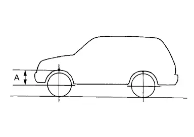
 NOTE:
NOTE:Note the measurements.
Set the wheel chocks on the rear tires.
Jack up front of the vehicle and set the rigid rack.
Remove the front tires.
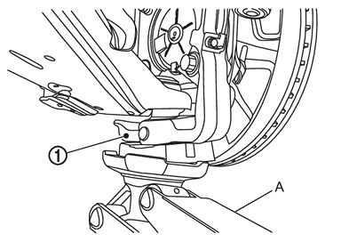
CAUTION:
Never damage threaded part of ball joint.
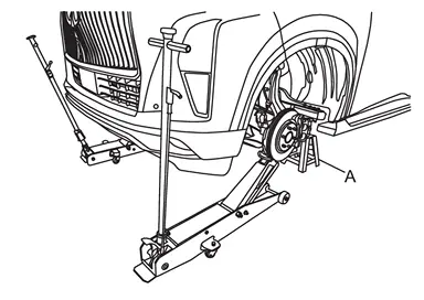
CAUTION:
Never damage steering knuckles.
Check the stable condition when using a suitable jack.
Never float the vehicle.
NOTE:Jack up left and right at the same time.
Measure between wheel center and fender arch (A).
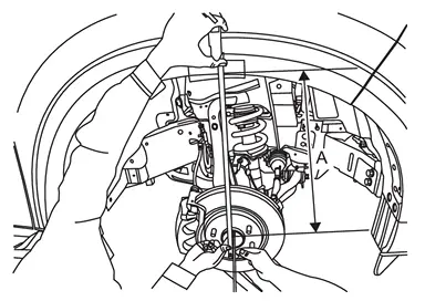
CAUTION:
Check the measurements are within +20 mm (0.79 in) from step 1.
If the measurements are +20 mm (0.79 in) or more, perform step 6 again.
Tight the mounting bolts of upper link (frame side) to the specified torque. Refer to Exploded View.
Perform inspection after installation. Refer to Inspection.
Perform adjustment after installation. Refer to Adjustment.
 Exploded View
Frame Upper link Steering knuckle : Always replace after every disassembly. : N·m (kg-m, ft-lb) ...
 Inspection
INSPECTION AFTER REMOVAL
Appearance
Check the following items, and replace the part if necessary.
Upper link and bushing for deformation, cracks or damage.
Ball joint boot for cracks or other damage, ...
Other materials:
Removal and Installation
REMOVAL
CAUTION:
Luggage Floor Rear Board
Remove luggage floor box. Refer to Removal and Installation.
Remove belt bracket mounting bolt of luggage floor rear board, and then remove luggage floor rear board.
Luggage Floor Board RH
Fold down the third seat RH forward.
Remove rope hook.Disengage r ...
Calibration of Yaw Rate Sensor
CAUTION:
Always perform the yaw rate sensor calibration before driving when the following operation is performed. Refer to Work Procedure.
×: Required —: Not required
Procedure Yaw rate sensor calibration Removing/ installing ABS actuator and electric unit (control unit) × Replacing ABS act ...
Exploded View
REMOVAL
Brake caliper assembly : N·m (kg-m, ft-lb)
DISASSEMBLY
Cap Bleeder valve Cylinder body Sliding pin Sliding pin boot Bushing Torque member : Vehicle front : N·m (kg-m, in-lb) : Apply rubber grease. ...

0.0055