
Nissan Armada 2025-2026 Service and Repair Manual: Removal and Installation
REMOVAL
Without Dynamic Digital Suspension and Electronic Air Suspension
Remove tires. Refer to ROAD WHEEL TIRE : Removal & Installation.
Remove wheel sensor and harness connector. Move wheel sensor in a place where it will not interfere with work. Refer to Removal and Installation.
Set suitable jack under rear lower link.
CAUTION:
Check the stable condition when using a suitable jack.
Never damage rear lower link.
Remove brake caliper assembly. Hang brake caliper assembly in a place where it will not interfere with work. Refer to Removal and Installation.
CAUTION:
Never depress brake pedal while brake caliper is removed.
Loosen rear lower link mounting nuts (frame side).
Separate rear lower link from axle housing. Refer to Removal and Installation.
Lower suitable jack, and remove coil spring. Refer to Removal and Installation.
CAUTION:
Check the stable condition when using a suitable jack.
Never damage rear lower link.
Set suitable jack under front lower link.
CAUTION:
Check the stable condition when using a suitable jack.
Never damage axle housing.
Separate front lower link from axle housing. Refer to Removal and Installation.
Remove shock absorber mounting bolts from front lower link. Refer to Removal and Installation.
Remove stabilizer connecting rods from front lower link. Refer to Removal and Installation.
Remove front lower link mounting bolt, nuts, stopper rubbers, eccentric disc, and adjusting bolt from frame, and remove front lower link.
Perform inspection after removal. Refer to Inspection.
With Dynamic Digital Suspension and Electronic Air Suspension
WARNING:
Start engine.
Turn OFF the electronic air suspension function. Refer to Operation.
Stop engine.
Lift up the vehicle.
Remove rear tire. Refer to ROAD WHEEL TIRE : Removal & Installation.
Disconnect shock absorber harness connector.
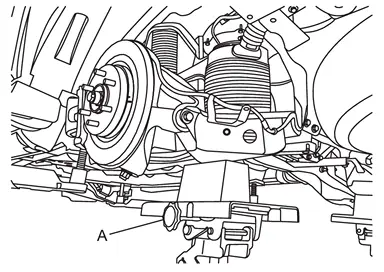
CAUTION:
Never damage rear lower link.
Check the stable condition when using a suitable jack.
Never lower the suitable jack until installation is completed.
Loosen the air connector  and perform air bleeding.
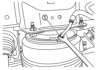
CAUTION:
Be careful since air flows swiftly from air tube.
Loosen the air connector slowly.
Never disconnect the air connector until the air completely bleeds.
Remove air tube together with air connector  from air spring
  .
.
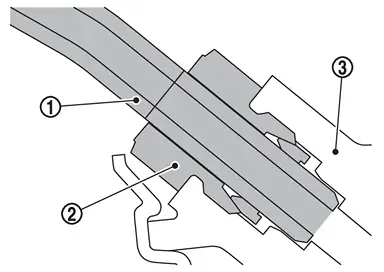
CAUTION:
Never damage air connector, air adapter, and air tube.
When reusing air connector, never remove air tube from air connector.
 NOTE:
NOTE:
Remove brake caliper assembly. Hang brake caliper assembly in a place where it will not interfere with work. Refer to Removal and Installation.
CAUTION:
Never depress brake pedal while brake caliper is removed.
Loosen rear lower link mounting nuts (frame side).
Separate rear lower link from axle housing. Refer to Removal and Installation.
Set suitable jack under front lower link.
CAUTION:
Check the stable condition when using a suitable jack.
Never damage axle housing.
Separate front lower link from axle housing. Refer to Removal and Installation.
Remove stabilizer connecting rods from front lower link. Refer to Removal and Installation.
Remove front lower link mounting bolt, nuts, stopper rubbers, eccentric disc, and adjusting bolt from frame, and remove front lower link.
Perform inspection after removal. Refer to Inspection.
INSTALLATION
Without Dynamic Digital Suspension and Electronic Air Suspension
Note the following, and install in the reverse order of removal.
Perform final tighting of front lower link (frame side) by the following procedures.
Measure between wheel center and fender arch (A).
NOTE:Note the measurements.
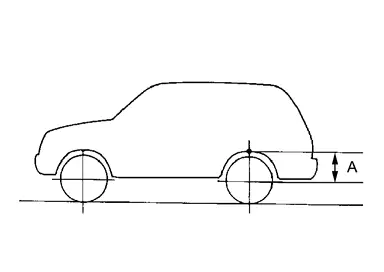
Set the wheel chocks on the front tires.
Jack up the rear of the vehicle and set the rigid rack.
Remove the rear tires.
CAUTION:
Never damage threaded part of ball joint.
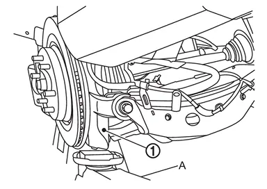
CAUTION:
Never damage axle housings.
Check the stable condition when using a suitable jack.
Never float the vehicle.
NOTE:Jack up left and right at the same time.
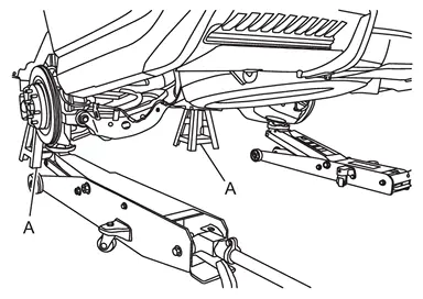
Measure between wheel center and fender arch (A).
CAUTION:
Check the measurements are within +20 mm (0.79 in) from step 1.
If the measurements are +20 mm (0.79 in) or more, perform step 6 again.
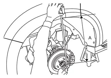
Tight the mounting nuts of front lower link (frame side) to the specified torque. Refer to Exploded View.
Perform inspection after installation. Refer to Inspection.
With Dynamic Digital Suspension and Electronic Air Suspension
Install front lower link mounting bolt, nuts, stopper rubbers, eccentric disc, and adjusting bolt to frame, and install front lower link.
CAUTION:
Never reuse mounting nut.
Install shock absorber to front lower link. Refer to Removal and Installation.
Install stabilizer connecting rods to front lower link. Refer to Removal and Installation.
Install front lower link to axle housing. Refer to Removal and Installation.
Install rear lower link to axle housing. Refer to Removal and Installation.
CAUTION:
Never reuse mounting nut.
CAUTION:
Never reuse mounting nut.
Install brake caliper assembly. Refer to Removal and Installation.
Install air tube and air connector together to air spring .
CAUTION:
Never damage air connector and air tube.
Never let foreign materials entered into parts.
Start engine.
Remove suitable jack from rear lower link.
Install shock absorber harness connector.
CAUTION:
Never twist or pull shock absorber harness, when installing.
Stop engine.
Install rear tire. Refer to ROAD WHEEL TIRE : Removal & Installation.
Lift down the vehicle.
Start engine.
Perform pressure measurements using CONSULT. Refer to Work Support.
NOTE:
Confirm that "Air suspension internal pressure judgement" is OK.
Perform the height sensor calibration using CONSULT. Refer to Work Support.
Use CONSULT and vehicle to the normal height. Refer to Work Support.
Turn ON the electronic air suspension function. Refer to Operation.
Stop engine.
Perform final tighting of front lower link (frame side) by the following procedures.Measure between wheel center and fender arch (A).
NOTE:
Note the measurements.
. (axle housing ball joint fastening part).
CAUTION:
Never damage threaded part of ball joint.
CAUTION:
Never damage axle housings.
Check the stable condition when using a suitable jack.
Never float the vehicle.
NOTE:
Jack up left and right at the same time.
CAUTION:
Check the measurements are within +20 mm (0.79 in) from step a.
If the measurements are +20 mm (0.79 in) or more, perform step f again.
Perform inspection after installation. Refer to Inspection.
 Exploded View
Frame Stopper rubber Axle housing Front lower link Eccentric disc Adjusting bolt : Always replace after every disassembly. : N·m (kg-m, ft-lb) ...
 Inspection
INSPECTION AFTER REMOVAL
Appearance
Check the following items, and replace the part if necessary.
Front lower link and bushing for deformation, cracks or damage.
Boot of ball joint for cracks or damag ...
Other materials:
Inspection Procedure
INSTRUMENT PANEL
Most incidents are caused by contact and movement between:
Cluster lid A and instrument panel
Acrylic lens and combination meter housing
Instrument panel to front pillar garnish
Instrument panel to windshield
Instrument panel mounting pins
Wiring harnesses behind the combination met ...
Removal & Installation
WARNING:
REMOVAL
Remove engine cover. Refer to Removal and Installation.
Disconnect battery cables from negative terminal. Refer to Removal and Installation.
Remove engine under cover front and front under cover using a power tool (commercial service tool). Refer to Removal and Installation and Remo ...
Heated seats
Basic information
WARNING
In the Nissan Armada, avoid using seat heaters if occupants are unable to
sense temperature changes or pain. Improper use may result in overheating and serious
injury.
CAUTION
Do not operate the heated seats in the Nissan Armada for extended periods
when not i ...

0.0063