
Nissan Armada 2025-2026 Service and Repair Manual: Removal and Installation
REMOVAL
WARNING:
CAUTION:
Never removal and install air suspension control module by holding air suspension control module harness.
Start engine.
Turn OFF the electronic air suspension function. Refer to Operation.
Stop engine.
Lift up the vehicle.
Remove rear LH tire. Refer to ROAD WHEEL TIRE : Removal & Installation.
Remove rear LH wheel house protector. Refer to Removal and Installation.
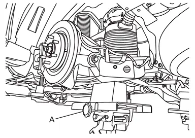
CAUTION:
Never damage rear lower link.
Check the stable condition when using a suitable jack.
Never lower the suitable jack until installation is completed.
Apply the matching marks  to the air tube
  when replacing air connector
  .
.
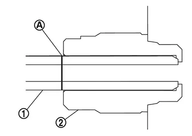
Loosen the each air connector and perform air bleeding.
CAUTION:
Be careful since air flows swiftly from air tube.
Loosen the air connector slowly.
Never disconnect the air connector until the air completely bleeds.
Remove breather hoses (exhaust) from air suspension LH duct assembly .
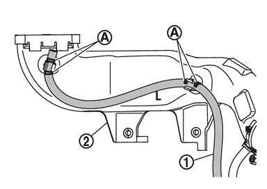
CAUTION:
Put matching marks on the breather hoses (exhaust).
Remove breather hose (intake) from air suspension LH duct assembly .
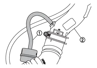
Unhook the pawls to remove the breather hoses from the air suspension control module .
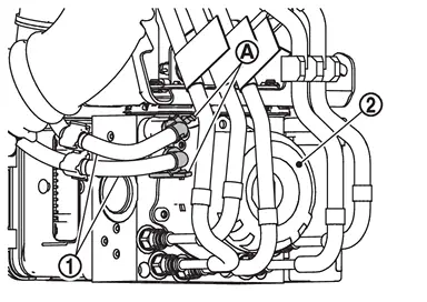
CAUTION:
Apply the matching marks to breather hoses and air suspension control module to confirm the installing position.
Never turn on the electronic air suspension function until the work is completed.
When reusing the air connector , remove air tubes and air connector together from air suspension control module  .
.
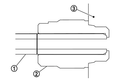
CAUTION:
Apply the matching marks to air tubes and air suspension control module to confirm the installing position.
Never damage air connector and air tube.
When reusing air connector, never remove air tube from air connector.
 NOTE:
NOTE:
When replacing the air connector, follow the procedure below.Fix part of the air connector, and remove part  of the air connector.
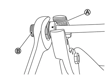
CAUTION:
Never damage air tube.
Slide the air connector part to direction , and remove the part  from the air tube .
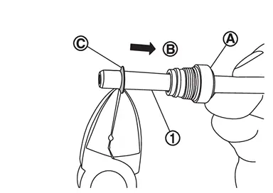
CAUTION:
Never damage air tube.
Remove the air connector part from the air tube .
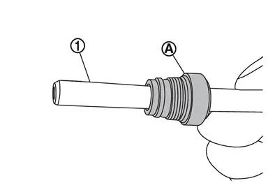
CAUTION:
Never damage air tube.
Remove harness clip and air tube clip form air suspension control module.
Remove bracket.
Disconnect air suspension control module harness connector , follow the procedure below.
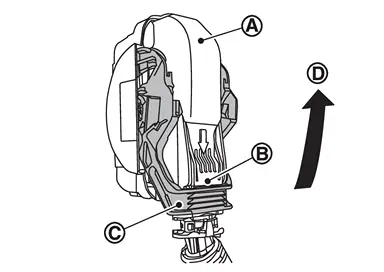
. Move the lever in the direction  until locked. Disconnect air suspension control module harness connector.
Remove air suspension control module from frame.
Remove bracket from air suspension control module if necessary.
INSTALLATION
Install bracket to air suspension control module if necessary.
Install air suspension control module to frame.
After installing the air suspension control module harness connector , move the lever in the direction to secure the locking.
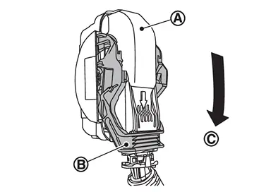
Install bracket.
Install harness clip and air tube clip to air suspension control module.
When reusing the air connector , and install air tubes and air connectors together to air suspension control module .
CAUTION:
When installing, align the matching marks which is applied when removing.
Never damage air connector and air tube.
Never remove the vinyl tape until installing the air tube and air connector.
Never let foreign materials entered into parts.
When replaced the air connector, follow the procedure below.Install air connectors to air suspension control module. Insert the air tube straight into the air connector to the marked point which is applied when removing.
CAUTION:
Securely insert the air tube with no damage and twist.
Never remove the air connector cover until air tube is installed.
Never let foreign materials entered into parts.
Install breather hoses to air suspension control module to secure the locking .
CAUTION:
When installing, align the matching marks which is applied when removing.
Never mistake the installing position of intake and exhaust.
Install connecting the end of breather hose (intake) to air suspension LH duct assembly , insert it up to position .
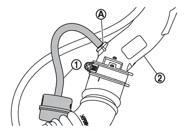
CAUTION:
Breather hose shall be assembled firmly without harmful scratches and twists on them.
Install breather hose (exhaust) to air suspension LH duct assembly , clip must be fixed between the matching marks of the breather hose (exhaust) made during removal.
CAUTION:
Breather hose shall be assembled firmly without harmful scratches and twists on them.
Start engine.
If replacing air suspension control module, perform "ADDITIONAL SERVICE WHEN REPLACING AIR SUSPENSION CONTROL MODULE". Refer to Work Procedure.
Perform "Air filling/pressure measurement " using CONSULT. Refer to Work Support.
Use CONSULT and fill the air. Follow the procedure below.Fill the air to the air tank for 180 seconds. Refer to Work Support. Fill the inner pressure of shock absorber (With Built In Air Spring) to 5.7 bar. Refer to Work Support. Fill the inner pressure of air spring to 3.3 bar. Refer to Work Support.
Remove suitable jack from rear lower link.
Stop engine.
Install rear LH wheel house protector. Refer to Removal and Installation.
Install rear LH tire. Refer to ROAD WHEEL TIRE : Removal & Installation.
Lift down the vehicle.
Start engine.
When replaced the air suspension control module, perform the height sensor calibration using CONSULT. Refer to Work Support.
Perform pressure measurements using CONSULT. Refer to Work Support.
NOTE:
Confirm that "Air suspension internal pressure judgement" is OK.
Use CONSULT and vehicle to the normal height. Refer to Work Support.
Turn ON the electronic air suspension function. Refer to Operation.
Stop engine.
Perform inspection after installation. Refer to Inspection.
Perform adjustment after installation. Refer to Adjustment.
 Exploded View
Air suspension LH duct assembly Breather hose (exhaust) Breather hose (intake) Air suspension control module Bracket Air connector Air tube Air suspension control module harness connector To ...
 Inspection
INSPECTION AFTER INSTALLATION
Perform the self-diagnosis using CONSULT. Check if any DTC is detected. Refer to CONSULT Function.
Confirm to close the hood.
Always check for the air leakage with soapy ...
Other materials:
Cumulative Battery Discharge Current Clear
CUMULATIVE BATTERY DISCHARGE CURRENT CLEAR is an operation to clear the cumulative value of battery discharge current which is memorized in IPDM E/R. This operation is necessary after replaced the 12V battery. Refer to Work Procedure.
NOTE:
The cumulative battery discharge current value is used for ...
Special Service Tools
Tool number
(TechMate No.)
Tool name Description KV40104001
(NI-53385)
Hub lock nut wrench
a: 85 mm (3.35 in)
b: 65 mm (2.56 in)
Removing and Installing wheel hub lock nut. KV40107300
(NI-51751)
Boot band crimping tool
Installing boot band KV38108000
( - )
Protector
a: 47 mm (1.85 in) dia.
b: ...
Security systems
Basic information
The Nissan Armada is equipped with two primary security systems designed to enhance
vehicle protection:
Vehicle security system
NISSAN Vehicle Immobilizer System
Vehicle Security System
Basic information
The Nissan Armada vehicle security system activates visual a ...

0.0057