
Nissan Armada 2025-2026 Service and Repair Manual: Removal and Installation
REMOVAL
CAUTION:
Drain engine coolant from cooling system. Refer to ENGINE COOLANT : Draining.
Disconnect front heater pipe assembly from front heater core. Refer to Removal and Installation.
Disconnect low-pressure pipe from front expansion valve. Refer to Removal and Installation.
Disconnect high-pressure pipe from front expansion valve. Refer to Removal and Installation.
Remove instrument panel assembly and steering member as a set. Refer to Removal and Installation.
Remove each duct.
Side ventilator duct (RH and 2 LH). Refer to Removal and Installation.
Center ventilator duct. Refer to Removal and Installation.
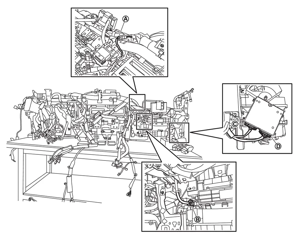
Disconnect harness connectors  ,
,  ,
,  , and
, and  .
.
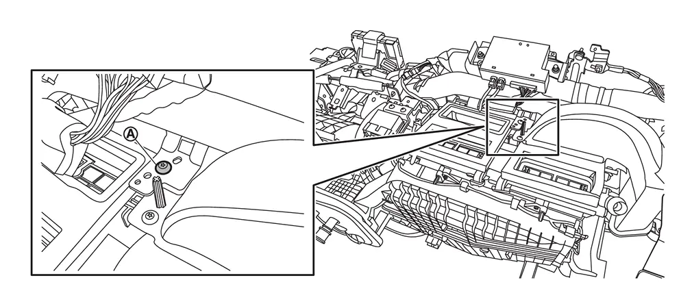
Remove front heater & cooling unit assembly fixing screw .
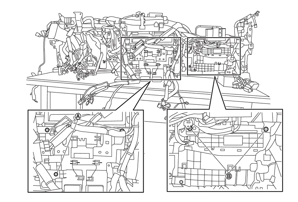
Remove front heater & cooling unit mounting bolts and front blower unit mounting bolts .
Remove front heater & cooling unit assembly and front blower unit assembly as a set.
CAUTION:
When removing front heater & cooling unit assembly, 2 workers are required to prevent it from dropping.
Remove each duct from front heater & cooling unit assembly.
Side ventilator duct 1 LH. Refer to Removal and Installation.
Front foot duct (RH and LH). Refer to Removal and Installation.
Remove front blower unit assembly from front heater & cooling unit assembly. Refer to Removal and Installation.
INSTALLATION
Note the following items, and then install in the reverse order of removal.
CAUTION:
 NOTE:
NOTE:
When filling radiator with engine coolant. Refer to ENGINE COOLANT : Refilling.

 Front Evaporator
...
Other materials:
Clamps
Generally speaking, when a body has to be straightened, the pulling device and the body must be attached to each other and the body itself must remain stationary. For this purpose, various clamps are used.
Common types of clamps and their characteristics are listed below:
DIRECTIONAL CHARACTERISTICS ...
Diagnosis Procedure
CHECK SYMPTOM
Check symptom (A or B)
Symptom A Display does not turn ON B Display is normal
Which symptom is detected?
A>>
GO TO 2.
B>>
GO TO 3.
CHECK POWER SUPPLY AND GROUND CIRCUIT
Check power supply and ground circuit. Refer to Diagnosis Procedure.
Is the inspection result nor ...
Work Procedure
FUEL PRESSURE RELEASE
FUEL PRESSURE RELEASE
Remove fuel pump fuse.
NOTE:
For the fuse number, Refer to Wiring Diagram.
For the fuse arrangement.
Start engine.
After engine stalls, crank it two or three times to release all fuel pressure.
Ignition switch OFF.
Reinstall fuel pump fuse after servicing ...

0.0051