
Nissan Armada 2025-2026 Service and Repair Manual: Work Procedure
FUEL PRESSURE RELEASE
FUEL PRESSURE RELEASE
Remove fuel pump fuse.
 NOTE:
NOTE:For the fuse number, Refer to Wiring Diagram.
For the fuse arrangement.
Start engine.
After engine stalls, crank it two or three times to release all fuel pressure.
Ignition switch OFF.
Reinstall fuel pump fuse after servicing fuel system.
INSPECTION END
LOW FUEL PRESSURE CHECK
CAUTION:
Before disconnecting fuel line, release fuel pressure from fuel line to eliminate danger.
The fuel hose connection method used when taking fuel pressure check must not be used for other purposes.
Be careful not to scratch or put debris around connection area when servicing, so that the quick connector maintains seal ability with O-rings inside.
Do not perform fuel pressure check with electrical systems operating (i.e. lights, rear defogger, A/C, etc.) Fuel pressure gauge may indicate false readings due to varying engine load and changes in manifold vacuum.
NOTE:
Prepare pans or saucers under the disconnected fuel line because the fuel may spill out. The fuel pressure cannot be completely released because this model does not have fuel return system.
FUEL PRESSURE CHECK
Release fuel pressure to zero.
Prepare fuel hose for fuel pressure check (B) and fuel tube adapter [SST: KV10120000 (-)] (D), then connect fuel pressure gauge (commercial service tool) (A).
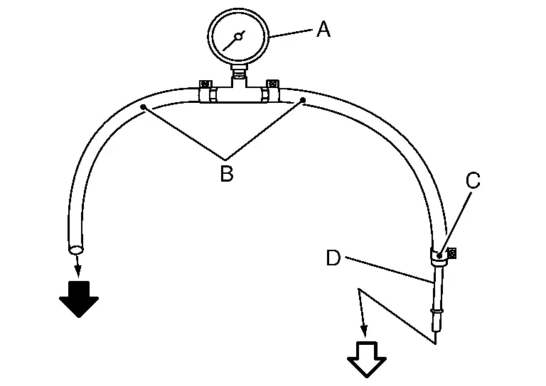

: To quick connector 
: To fuel tube (engine side) C : Clamp CAUTION:
Use suitable fuel hose for fuel pressure check (genuine NISSAN fuel hose without quick connector).
To avoid unnecessary force or tension to hose, use moderately long fuel hose for fuel pressure check.
Do not use the fuel hose for checking fuel pressure with damage or cracks on it.
Use Pressure Gauge to check fuel pressure.
Remove fuel hose.
CAUTION:
Do not twist or kink fuel hose because it is plastic hose.
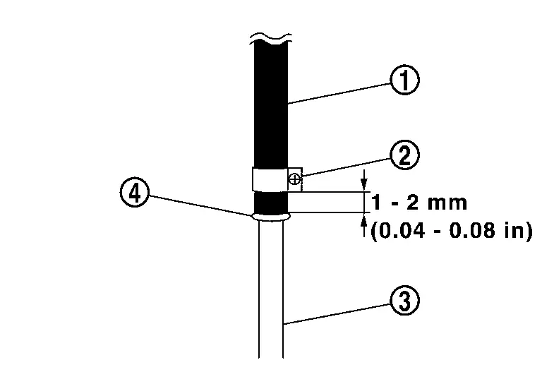
Connect fuel hose for fuel pressure check (1) to fuel tube (engine side) (3) with clamp (2) as shown in the figure.
CAUTION:
Wipe off oil or dirt from hose insertion part using cloth moistened with gasoline.
Apply proper amount of gasoline between top of the high pressure fuel pump (3) and spool (4).
Insert fuel hose for fuel pressure check until it touches the spool on high pressure fuel pump.
Use NISSAN genuine hose clamp (part number: 16439 N4710 or 16439 40U00).
When reconnecting fuel line, always use new clamps.
Use a torque driver to tighten clamps.
Tightening torque: 1.0 - 1.5 N·m (0.1 - 0.15 kg-m, 9 - 13 in-lb) Install hose clamp to the position within 1 - 2 mm (0.04 - 0.08 in).
Make sure that clamp screw does not contact adjacent parts.
After connecting fuel hose for fuel pressure check, pull the hose with a force of approximately 98 N (10 kg, 22 lb) to confirm high pressure fuel pump does not come off.
Connect fuel tube adapter to quick connector.
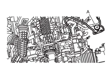
A :Fuel pressure gauge Ignition switch ON and check for fuel leakage.
Start engine and check for fuel leakage.
Stop the engine.
Ignition switch ON and read the indication of fuel pressure gauge.
CAUTION:
Do not perform fuel pressure check with system operating. Fuel pressure gauge may indicate false readings.
During fuel pressure check, confirm for fuel leakage from fuel connection every 3 minutes.
At ignition switch ON : Approximately 500 kPa (5.0 bar, 5.1 kg/cm2, 72.5 psi)
Is the inspection result normal?
YES>>INSPECTION END
NO>>GO TO 2.
CHECK FUEL HOSES
Check the following.
Fuel hoses for clogging
Fuel filter for clogging
Low pressure fuel pump
Fuel pressure regulator for clogging
Is the inspection result normal?
YES>>Replace fuel pressure regulator.
NO>>Repair or replace error-detected parts.
HIGH FUEL PRESSURE CHECK
NOTE:
Since the fuel pressure gauge kit cannot be connected, follow the method shown below to check high fuel pressure.
 WITH CONSULT
Start engine.
Check “Fuel pressure sensor voltage� in “Data monitor� mode with CONSULT.
Monitor Item Condition Values/Status Fuel pressure sensor voltage Idle 1.6V 2,000 rpm 1.5-2.1V
 WITHOUT CONSULT
Start the engine.
Check fuel rail pressure sensor signal voltage.
| + | − | Condition | Value (Approx.) | |
|---|---|---|---|---|
| Fuel rail pressure sensor | ||||
| Connector | Terminal | |||
| F52 | 2 | Ground | Engine speed: idle | 1.6V |
| 2,000 rpm | 1.5-2.1V | |||


Other materials:
Exploded View
REMOVAL
Front wiper blade RH Front wiper arm RH Front wiper arm cap Front wiper drive assembly Front wiper arm LH Front wiper blade LH : N·m (kg-m, in-lb) : N·m (kg-m, ft-lb)
DISASSEMBLY
Front wiper linkage Front wiper pivot assembly Pivot cover Front wiper motor assembly : Body gr ...
Exploded View
Oil pump drive chain Oil pump sprocket Oil pump drive sprocket Oil pump drive chain tensioner Oil pump assembly O-ring Oil pump seal O-ring Oil strainer Comply with the installation procedure when tightening. Refer to Removal and Installation : Engine front : Always replace after every ...
Removal and Installation
WARNING:
REMOVAL
CAUTION:
Never drain engine oil when the engine is hot to avoid the danger of being scalded.
Remove front under cover using a power tool (commercial service tool). Refer to Removal and Installation.
Remove front cross member assembly.
Drain engine oil. Refer to Draining.
Remove engi ...

0.0058