
Nissan Armada 2025-2026 Service and Repair Manual: Removal and Installation
WORK STEP
When removing instrument panel assembly and display unit take steps in the order shown by the numbers below.
| PARTS | INSTRUMENT PANEL ASSEMBLY | DISPLAY UNIT |
|---|---|---|
| Dash side finisher RH | [1] | |
| Instrument lower cover RH | [2] | |
| Glove box assembly | [3] | |
| Passenger knee air bag module | [4] | |
| Instrument mask LH | [5] | |
| Dash side finisher LH | [6] | |
| Instrument lower panel LH | [7] | |
| Driver air bag module | [8] | |
| Steering wheel | [9] | |
| Steering column cover upper and lower | [10] | |
| Spiral cable | [11] | |
| Instrument pad A | [12] | [1] |
| Display unit finisher LH | [13] | [2] |
| Display unit cover | [14] | [3] |
| Display unit and display unit finisher RH | [15] | [4] |
| Instrument mask RH | [16] | |
| Front center console body assembly | [17] | |
| Instrument pad D | [18] | |
| Instrument pad B | [19] | |
| Cluster lid A | [20] | |
| Front pillar garnish | [21] | |
| Front speaker grille | [22] | |
| Center instrument lower panel | [23] | |
| Instrument finisher C | [24] | |
| Instrument finisher A | [25] | |
| Instrument finisher B | [26] | |
| Drain hose | [27] | |
| Steering column assembly | [28] | |
| Harness connectors and harness fixing clips | [29] | |
| Cowl top cover | [30] | |
| Steering member stay LH | [31] | |
Steering member assembly (with all parts under the instrument panel assembly as a set) | [32] | |
| Instrument panel assembly | [33] |
[]: Number indicates step in removal procedure.
REMOVAL
WARNING:
Before servicing, disconnect battery negative terminal. Refer to Precautions for Removing Battery Terminal.
CAUTION:
Before servicing, move steering wheel most lower and rearward position.
When removing, always use a remover tool that is made of plastic.
Always apply the parking brake before performing removal and installation.
 NOTE:
NOTE:
To replacing the in-cabin microfilter, disengage fixing pawls according to arrows direction as shown in the figure, and then remove glove box lid inner.
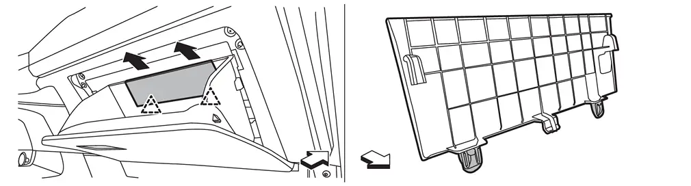
 | : Pawl |
 | : Vehicle front |
Remove dash side finisher RH. Refer to Removal and Installation.
Remove instrument lower cover RH. Refer to Removal and Installation.
Remove glove box assembly.Remove glove box assembly fixing screws  .
.
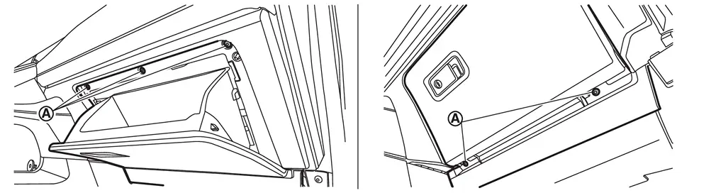
| : Pawl |
 | : Metal clip |
Remove passenger knee air bag module. Refer to .Removal and Installation
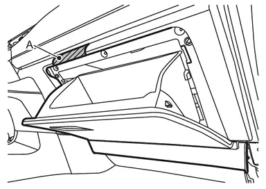
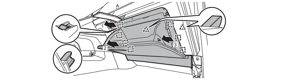
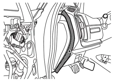
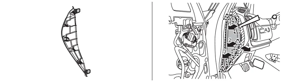
Remove instrument mask LH.Apply protective tape (A) on the part to protect it from damage.
| : Pawl |
| : Metal clip |
Remove dash side finisher LH. Refer to Removal and Installation.
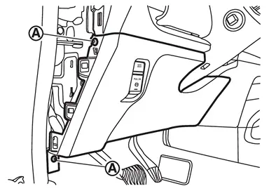
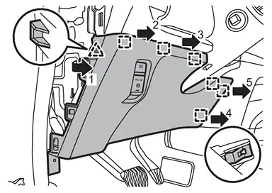
Remove instrument lower panel LH.Remove instrument lower panel LH fixing screws .
| : Pawl |
| : Metal clip |
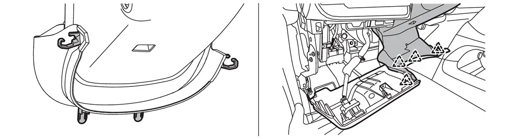
| : Pawl |
Remove driver air bag module. Refer to Removal and Installation.
Remove steering wheel. Refer to Removal and Installation.
Remove steering column cover upper and lower.Remove steering column cover upper and lower fixing screws .
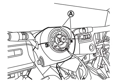
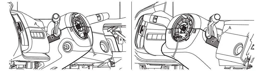
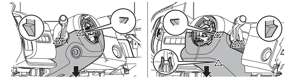
| : Pawl |
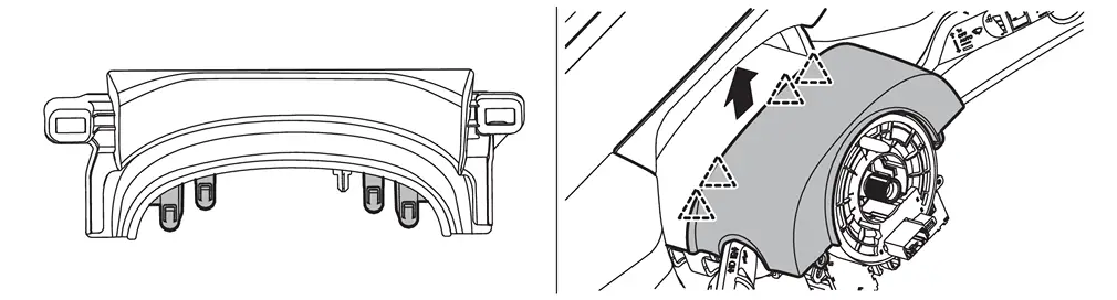
| : Pawl |
Remove spiral cable. Refer to Removal and Installation.
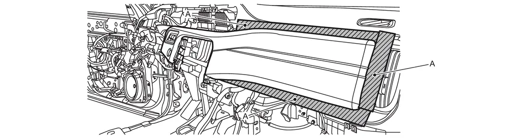
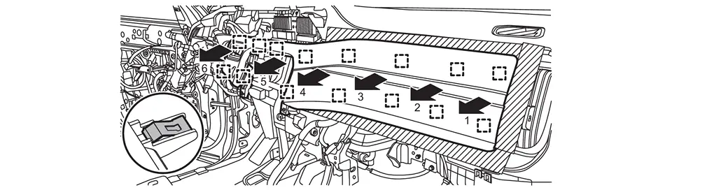
Remove instrument pad A.Apply protective tapes (A) on the part to protect it from damage.
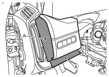
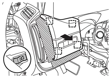
| : Metal clip |
Remove display unit finisher LH.Apply protective tape (A) on the part to protect it from damage.
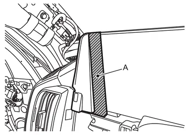
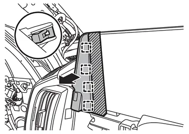
| : Metal clip |
Remove display unit cover.Apply protective tapes (A) on the part to protect it from damage.
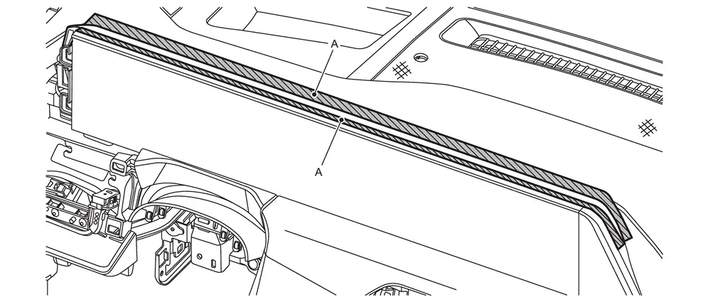
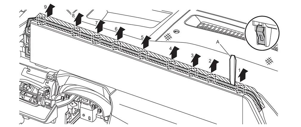
| : Metal clip |
Remove display unit and display unit finisher RH.Remove display unit with display unit finisher RH as a set. Refer to Removal & Installation. Disengage fixing metal clips, and then remove display unit finisher RH from display unit.
Remove instrument mask RH.Apply protective tape (A) on the part to protect it from damage.
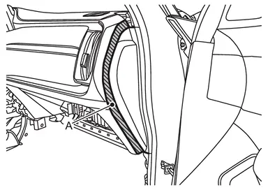
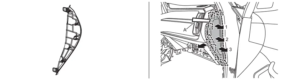
| : Pawl |
| : Metal clip |
Remove front center console body assembly. Refer to Removal and Installation.
Remove instrument pad D.Remove instrument pad D fixing screws .
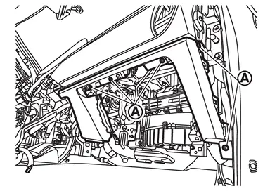
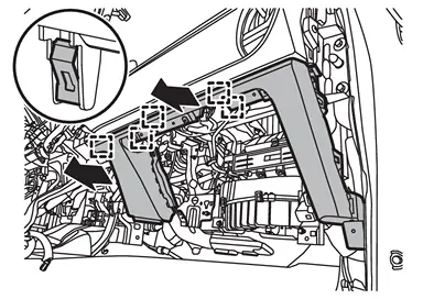
| : Metal clip |
Remove instrument pad B.Remove instrument pad B fixing screw .
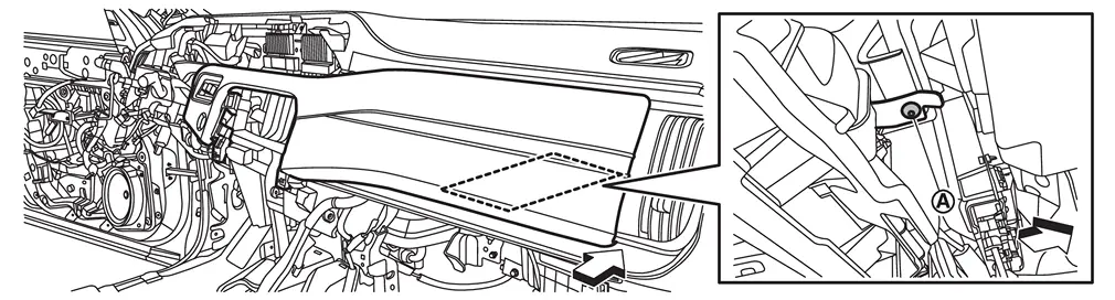
| : Vehicle front |
| : Metal clip |
Disengage fixing metal clips, and then remove cluster lid A.
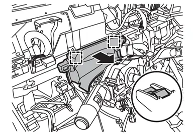
| : Metal clip |
Remove front pillar garnish. Refer to Removal and Installation.
Remove front speaker grille.Disengage fixing pawls and metal clips according to numerical order 1→8 indicated by arrows as shown in the figure.
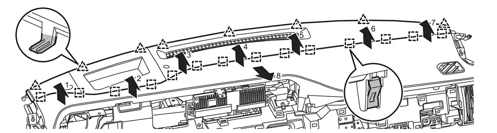
| : Pawl |
| : Metal clip |
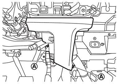
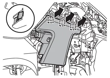
Remove center instrument lower panel.Remove center instrument lower panel fixing screws .
| : Metal clip |
Disengage fixing metal clips, and then remove instrument finisher C.
| : Metal clip |
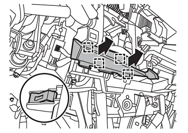
Remove instrument finisher A.Disconnect harness connector (if equipped). Remove fixing screw .
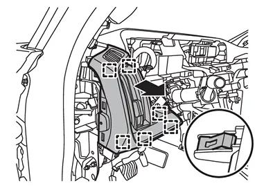
| : Metal clip |
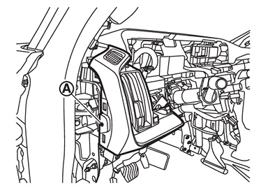
Remove Instrument finisher B.Disconnect harness connector (if equipped). Remove fixing screws .
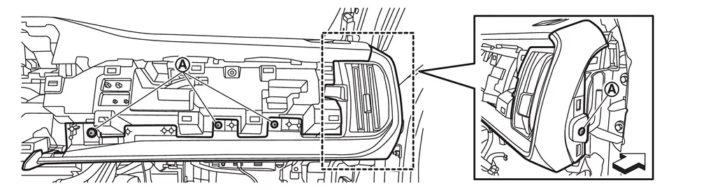
| : Vehicle front |
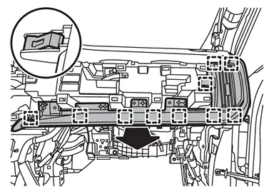
| : Metal clip |
Disconnect drain hose according to arrow direction as shown in the figure.
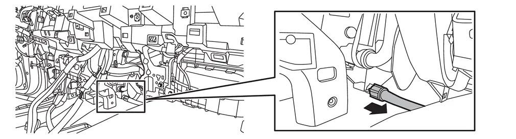
Remove steering column assembly mounting portion from steering member assembly to secure work space. Refer to Removal and Installation.
NOTE:
No need to removing steering column assembly completely from vehicle. After removed steering column assembly mounting portion, put on it jack stand, etc.
Disconnect harness connectors and disengage harness fixing clips position as necessary.
Remove cowl top cover. Refer to Removal and Installation.
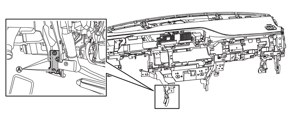
Remove mounting nuts , and then remove steering member stay LH.
Remove mounting bolts , and then remove steering member assembly with all parts under the instrument panel assembly as a set from the vehicle.
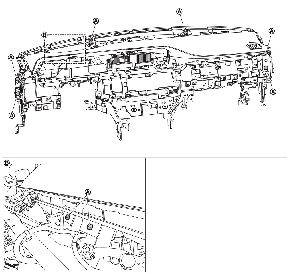
| : Vehicle front |
CAUTION:
Prepare the work table, stand jack, etc. to put on steering member assembly and all parts under the instrument panel assembly as a set before removed it.
2 or more workers are required to prevent it from dropping/damaging when removing steering member assembly because its are heavy components.
Remove instrument panel assembly from steering member assembly.Remove fixing screw , and then remove instrument panel bracket.
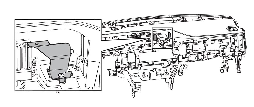
.
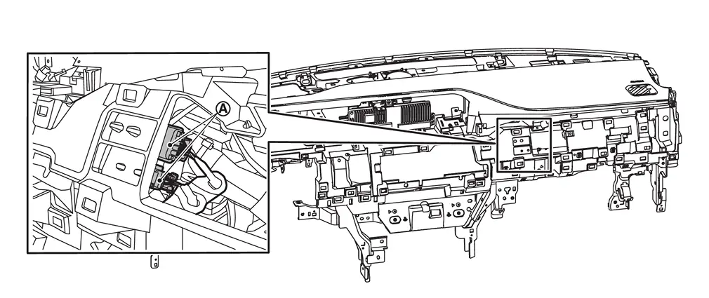
.
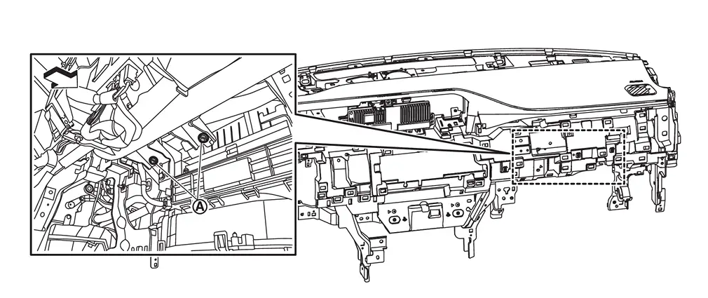
| : Vehicle front |
, and then remove instrument panel assembly from steering member assembly.
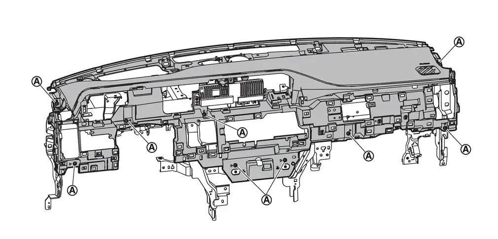
GPS antenna: Refer to Removal & Installation.
Telematics antenna: Refer to Removal & Installation.
Passenger air bag module: Refer to Removal and Installation.
Sub harness.
INSTALLATION
Note the following items, and then install in the reverse order of removal.
CAUTION:
Never reuse the passenger air bag module mounting bolts after removal, replace with the new bolts.
NOTE:
If glove box assembly replace to new one, install new glove box lid lock key cylinder and sleeve. Refer to Removal and Installation.
 Exploded View
INSTRUMENT PANEL ASSEMBLY
Front speaker grille*1 Display unit cover Display unit Instrument panel assembly Instrument mask LH Instrument finisher A Display unit finisher LH Instrument pad A S ...

Other materials:
Removal and Installation
CAUTION:
Never move intelligent rear view mirror beyond the movable range as the wiring may break.
: Vehicle front
intelligent rear view mirror movable range A : Standard position B : Less than 20° (upward adjustment range) C : Less than 20° (downward adjustment range) D : Less than ...
Disassembly and Assembly
DISASSEMBLY
Disengage the pawl and turn EVAP canister vent control valve counterclockwise.
: Lock : Unlock
Remove the EVAP canister vent control valve.
ASSEMBLY
Assemble in the reverse order of disassembly.
CAUTION:
Do not reuse O-rings. ...
How to enable/disable the I-LI system
Example
ProPILOT Assist switch
Vehicle information display
Steering-wheel-mounted control (right side)
Basic information
In the Nissan Armada, the Intelligent Lane Intervention (I-LI) system can be
configured through the vehicle information display and steering wheel controls,
pr ...

0.0054