
Nissan Armada 2025-2026 Service and Repair Manual: Exploded View
INSTRUMENT PANEL ASSEMBLY
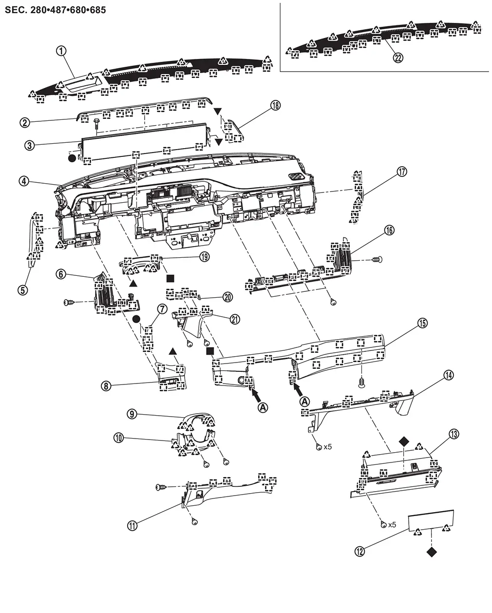
 | Front speaker grille*1 |  | Display unit cover |  | Display unit |
 | Instrument panel assembly |  | Instrument mask LH |  | Instrument finisher A |
 | Display unit finisher LH |  | Instrument pad A |  | Steering column cover upper |
 | Steering column cover lower |  | Instrument lower panel LH |  | Glove box lid inner |
 | Glove box assembly |  | Instrument pad D |  | Instrument pad B |
 | Instrument finisher B |  | Instrument mask RH |  | Display unit finisher RH |
 | Cluster lid A |  | Instrument finisher C |  | Center instrument lower panel |
 | Front speaker grille*2 | ||||
 | From front center console switch finisher assembly | ||||
 | : Pawl | ||||
 | : Metal clip | ||||
 , ,  , ,  , ,  , ,  : Indicates that the part is connected at points with same symbol in actual vehicle. : Indicates that the part is connected at points with same symbol in actual vehicle. | |||||
*1: With Head Up Display models
*2: Without Head Up Display models
STEERING MEMBER ASSEMBLY
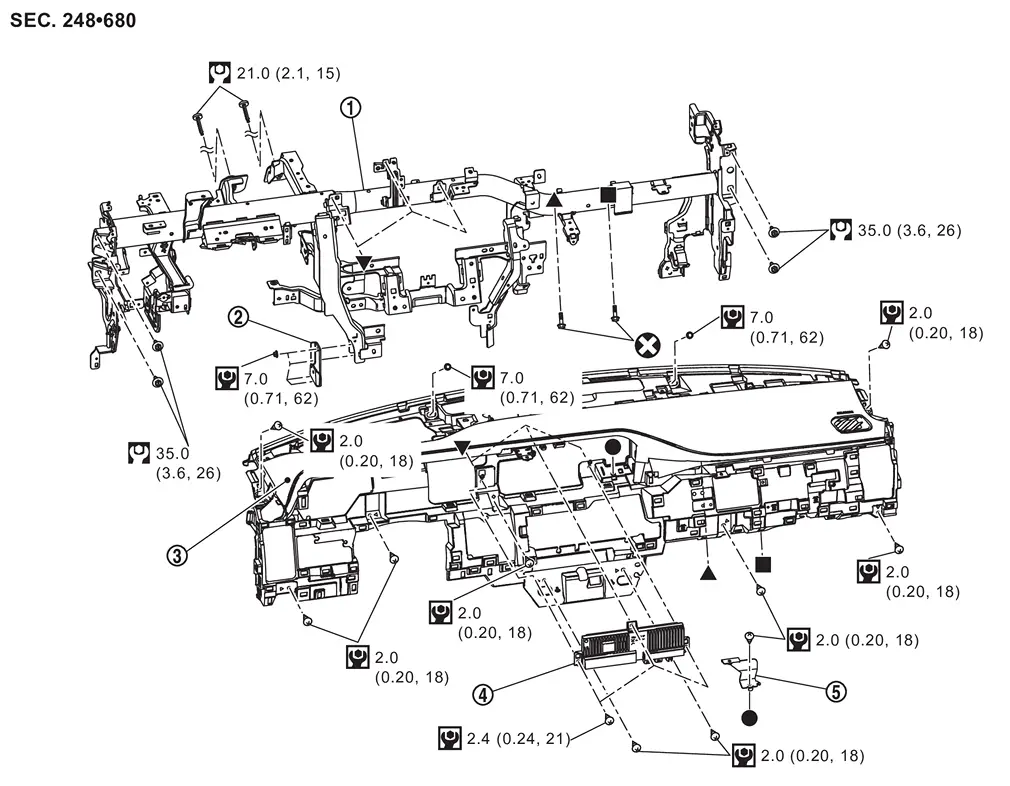
| Steering member assembly | | Steering member stay LH | | Instrument panel assembly |
| Combination meter | | Instrument panel bracket | ||
 | : Always replace after every disassembly. | ||||
 | : N·m (kg-m, in-lb) | ||||
 | : N·m (kg-m, ft-lb) | ||||
| , , , : Indicates that the part is connected at points with same symbol in actual vehicle. | |||||

 Removal and Installation
WORK STEP
When removing instrument panel assembly and display unit take steps in the order shown by the numbers below.
PARTS INSTRUMENT PANEL ASSEMBLY DISPLAY UNIT Dash side finisher RH [1] Ins ...
Other materials:
Work Flow
DETAILED FLOW
INTERVIEW FROM THE CUSTOMER
CAUTION:
>>
GO TO 2.
CHECK SYMPTOM
CAUTION:
>>
GO TO 3.
PERFORM SELF-DIAGNOSIS
With CONSULT
Perform self-diagnosis for “CHASSIS CONTROL�.
Is DTC detected?
YES>>
Record or print self-diagnosis results and freeze frame data (FFD). ...
Diagnosis Procedure
Possible cause Inspection item Reference page ProPILOT Assist switch is stuck ADAS control unit 2: Check "MAIN SW" of data monitor item Diagnosis Description Check self-diagnosis result of ADAS control unit 2 DTC Index ECM cannot read ON/OFF of ProPILOT Assist switch Check self-diagnosis r ...
Removal and Installation
WARNING:
REMOVAL
CAUTION:
When removing the A/T assembly from engine, first remove the crankshaft position sensor (POS) from the A/T assembly.
Be careful not to damage sensor edge.
When replacing A/T assembly, Perform "ADDITIONAL SERVICE WHEN REPLACING TRANSMISSION ASSEMBLY". Refer to Description.
...

0.0085