
Nissan Armada 2025-2026 Service and Repair Manual: Removal and Installation
CAUTION:
Always work with 2 workers, because it is heavy weight.
REMOVAL
Remove headrest.
Slide second seat to front most position.
Disengage fixing pawls using a remover tool (A) according to numerical order 1→3 indicated by arrows as shown in the figure, and then remove center rail finisher (LH seat).
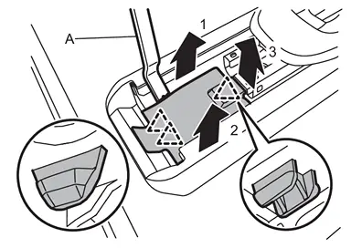
 | : Pawl |
Remove rear side mounting bolts of second seat assembly.
Slide second seat to rear most position.
Remove inside and outside seat leg cover.
LH seat
Disengage fixing pawls using a remover tool (A) according to numerical order 1→2 indicated by arrows as shown in the figure, and then remove inside seat leg cover (LH seat)
 and outside seat leg cover (LH seat)
  .
.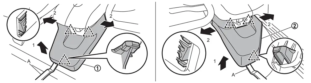
: Pawl RH seat
Disengage fixing pawls using a remover tool (A) according to numerical order 1→2 indicated by arrows as shown in the figure, and then remove outside seat leg cover (RH seat)
and inside seat leg cover (RH seat) .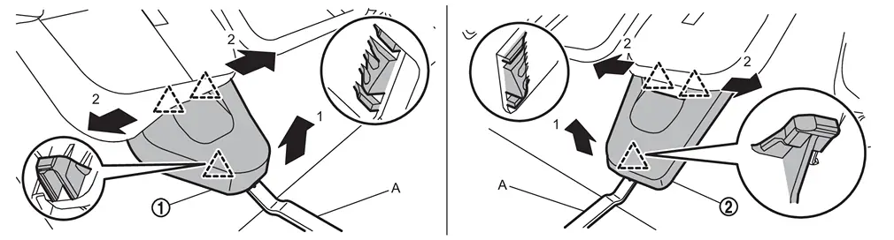
: Pawl
Remove front side mounting bolts of second seat assembly.
Pull up second seat to rearward.
Disengage body harness fixing clip, and then disconnect harness connector.
CAUTION:
Remove second seat assembly from vehicle.
 NOTE:
NOTE:
If disassemble second seat after removing, move second seat to walk in condition to ensure the workspace for disassembling seat cushion finisher.
INSTALLATION
Note the following items, and then install in the reverse order of removal.
CAUTION:
Before installing seat to vehicle, check the slide rail locking position which inner and outer side. They should be locking same position.
When installing, tighten mounting bolts according to the numerical order 1→4 or 1→5 as shown in the figure.
LH seat
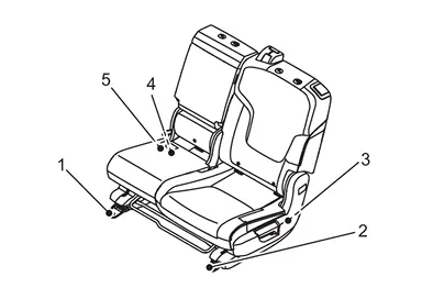
RH seat
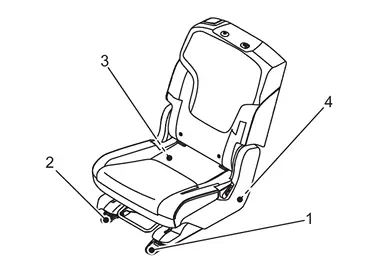
Tighten seat mounting bolts to the specified torque. Refer to Exploded View.
 Exploded View
REMOVAL
Outer headrest Second seat assembly
(RH seat) Outside seat leg cover (RH seat) Inside seat leg cover (RH seat) Inside seat leg cover (LH seat) Outside seat leg cover (LH seat) Second se ...
 Second Seatback
...
Other materials:
Precautions for Removing Battery Terminal
NOTE:
NOTE:
NOTE:
The removal of 12V battery may cause a DTC detection error.
HOW TO DISCONNECT 12V BATTERY TERMINAL
Disconnect 12V battery terminal according to instruction described below.
Open the hood.
Turn ignition switch to the ON position.
Turn ignition switch to the OFF position with the d ...
Inspection
WARNING:
INSPECTION
Uneven wear
Check the uneven wear of the disc rotor using a micrometer. Replace the disc rotor if the thickness is below the wear limit.
2WD: Refer to Removal and Installation.
4WD: Refer to Removal and Installation.
Thickness variation (measured at 8 positions) : Refer to Fr ...
Work Procedure
WARNING:
UNIT CHARACTERISTIC VALUE CONFIRMATION
: Side surface : Top surface
NOTE:
There is space on the top to check with the camera.
>>
GO TO 2.
WRITING UNIT PARAMETER
With CONSULT
Ignition switch ON.
Select “Work support� in “AWD/4WD�.
Perform “Unit parameter writing� to t ...

0.0066