
Nissan Armada 2025-2026 Service and Repair Manual: Removal and Installation
WARNING:
CAUTION:
To reduce the vehicle weight and prevent side sill deformation, remove the following parts before lift up the vehicle.
Front door assembly. Refer to Removal and Installation.
Rear door assembly. Refer to Removal and Installation.
Front seat. Refer to Removal and Installation.
Second seat. Refer to Removal and Installation (captain seat) or Removal and Installation (bench seat).
Third seat. Refer to Removal and Installation.
Side step. Refer to Removal and Installation.
Never lift up by body side sill using 2-pole lift before separating body assembly from frame assembly. Otherwise, body may be damaged.
PREPARATION FOR SEPARATION OF FRAME ASSEMBLY AND BODY ASSEMBLY
Set arms of 2-pole lift to lifting point of frame assembly. Refer to 2-Pole Lift.
CAUTION:
After the preparation of separation is finished, body assembly will be lifted up. When doing that, lift arms need to set on body assembly.
Therefore, the vehicle position must be an appropriate position to perform for both operations.
Remove/Disconnect the Parts Installed in Vehicle Front Part
Perform the following works.
Remove engine under cover. Refer to Removal and Installation.
Discharge refrigerant. Refer to Recycle Refrigerant.
Drain brake fluid. Refer to Draining.
Drain engine coolant. Refer to ENGINE COOLANT : Draining.
Drain A/T fluid. Refer to Changing.
Remove all tires and wheels. Refer to ROAD WHEEL TIRE : Removal & Installation.
Remove fender protector (LH and RH). Refer to Removal and Installation.
Remove front bumper fascia and front bumper retainer upper. Refer to Removal and Installation (OFF ROAD MODEL) or Removal and Installation (CITY MODEL).
Disconnect brake tubes inside front fender (LH and RH). Refer to Removal and Installation.
Disconnect front wheel sensor harness connectors. Refer to Removal and Installation.
Disconnect shock absorber harness connector (with air suspension models). Refer to Removal and Installation.
Disconnect engine room harness connectors and remove harness clips from engine assembly (engine RH side). Refer to Harness Layout.
Remove 12V battery and battery tray. Refer to Removal and Installation.
Remove heater hose from front heater pipe assembly. Refer to Removal and Installation.
Remove radiator hose (upper and lower). Refer to RADIATOR : Removal & Installation.
Remove radiator reservoir tank. Refer to RADIATOR : Exploded View.
Remove air cleaner cover and air duct 1. Refer to Removal and Installation.
Remove air inlet tube 1 and 2 from charge air cooler. Refer to Removal & Installation.
Remove A/T fluid cooler hose A and B from A/T fluid cooler tube assembly. Refer to Removal and Installation.
Remove A/C low-pressure flexible hose from A/C low-pressure pipe. Refer to Removal and Installation.
Remove A/C high-pressure flexible hose from condenser. Refer to Removal and Installation.
Separate lower joint from steering shaft. Refer to Removal and Installation.
CAUTION:
Remove/Disconnect the Parts Installed in Vehicle Center Part
Disconnect harness connector on frame assembly RH center side.
Remove fixing clip and disengage fixing pawl, and then remove harness connector protector.
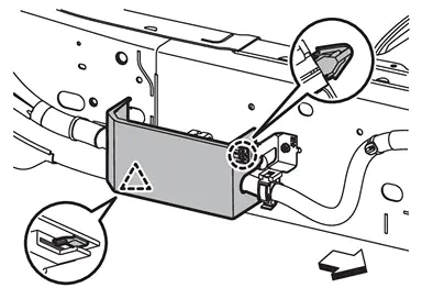

: Clip 
: Pawl 
: Vehicle front Remove harness bracket bolts
 , and then remove harness brackets.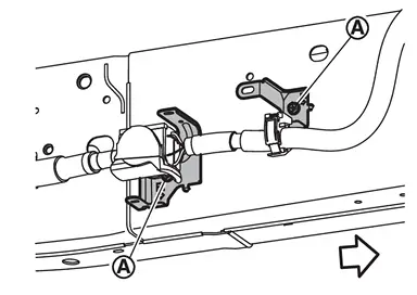
: Vehicle front Disconnect harness connector.
Remove/Disconnect the Parts Installed in Vehicle Rear Part
Perform the following works.
Remove rear bumper fascia. Refer to Removal and Installation.
Remove rear wheel house protector (LH and RH). Refer to Removal and Installation.
Remove fuel filler base mask. Refer to Removal and Installation.
Remove fuel filler tube protector 1 and fuel filler tube 1 mounting bolts. Refer to FUEL TANK : Removal & Installation.
Disconnect air suspension duct assembly from air suspension (LH and RH) duct assembly (with air suspension models). Refer to Removal and Installation.
REMOVAL
Install all tires and wheels. Refer to ROAD WHEEL TIRE : Removal & Installation.
Unload the vehicle from lift.
Set arms of 2-pole lift to lifting point of body assembly.
CAUTION:
Use a lift pad with a groove.
Set lift arms on side sill between approximately 60 mm (2.4 in) (A) from the front end and approximately 350 mm (13.8 in) (B) from the rear end as shown in figure.
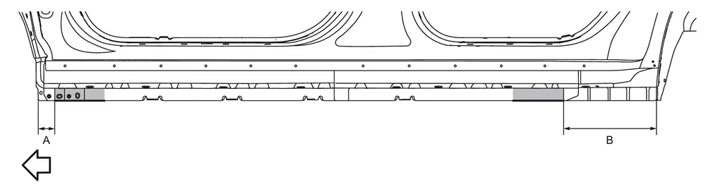
: Vehicle front When lifting the body assembly, open the lift arms as wide as possible and ensure that the front and rear of the body assembly are well balanced.
Apply matching tapes (A) to all tires.
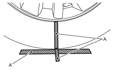
 NOTE:
NOTE:
If the body assembly or frame assembly move after separating the body assembly and frame assembly, initial position mark will help to set the body assembly and frame assembly installation position.
Remove all cab mounting insulator mounting bolts.
Slowly lift up the body assembly using 2-pole lift.
CAUTION:
Lift up the body assembly approximately 50 mm (2.0 in) at a time, check that there is no interference with the frame assembly and all connection points are disconnected.
Support the fuel filler tube to prevent interference with the body assembly.
Remove cab mounting insulator (2nd) and (4th) mounting nuts.
Remove cab mounting insulator.
INSTALLATION
Note the following items, and then install in the reverse order of removal.
CAUTION:
When assembling the body assembly and frame assembly, set the target guide bars on the front left side and rear right side to guide the assembly position.
Set the guide bars to the locate holes on the frame assembly.
Unit: mm [in]
Length Diameter Guide bar size Approx. 400 - 500 [15.8 - 19.7] Approx. Φ15 [0.6] Down the body assembly
 while checking that the position of guide bars (E) and locate holes
  on body assembly are matched.
When confirmed that the tip of guide bars are inserted to the locate holes on body assembly, down the body assembly until contact to cab mounting insulators.
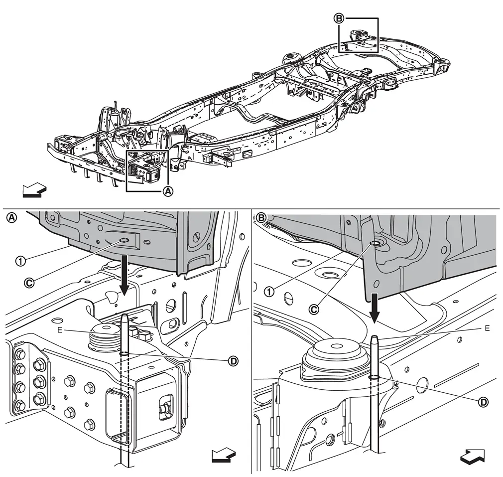

: Locate hole on frame assembly : Vehicle front Remove the guide bars.
After installation, perform "ADDITIONAL SERVICE WHEN REPLACING FRONT CAMERA UNIT". Refer to Work Procedure.
After installation, perform camera aiming. Refer to Work Procedure.
After installation, perform the camera calibration (with around view monitor models). Refer to Work Procedure.
After installation, perform side radar alignment (with side radar). Refer to Inspection [front side (CITY MODEL)], Inspection (rear side).
After installation, perform inspection of steering shaft. Refer to Inspection.
Before starting engine, charge the refrigerant. Refer to Charge Refrigerant.
Before starting engine, check oil/fluid levels including engine coolant and engine oil. If levels are less than the required quantity, fill to the specified level. Refer to Fluids and Lubricants.
Warm up engine thoroughly to check that there is no leakage of fuel, exhaust gases, or any oil/fluids including engine oil and engine coolant.
After installation is completed, perform self-diagnosis using CONSULT and confirm if the system is normal.
 Exploded View
Cab mounting insulator (1st) Cab mounting insulator (2nd) Cab mounting insulator (3rd) Cab mounting insulator (4th) Front bumper cross member Rear engine mounting cross member Chipping protect ...

Other materials:
Work Flow
Without ProPILOT Assist 2.1
OVERALL SEQUENCE
DETAILED FLOW
INTERVIEW FOR MALFUNCTION
It is important to clarify the customer’s concerns before starting the inspection. Interview the customer about the concerns carefully and understand the symptoms fully.
NOTE:
The customers are not professionals ...
Symptom Table
NOTE:
For Navigation system operation information, refer to Navigation system Owner's Manual.
BASIC OPERATIONS
Symptom Possible cause Possible solution No image is displayed. The brightness is at the lowest setting. Adjust the brightness of the display. The systems in the video mode. Press â ...
Removal and Installation
REMOVAL
Remove the instrument lower panel LH. Refer to Removal and Installation.
Remove parking brake switch mounting screws , and then remove parking brake switch .
: Instrument lower panel LH
INSTALLATION
Install in the reverse order of removal. ...

0.0067